B3) FORWARD CONTROL CABLE
(Fig. 5 ref. C point b , and ref. D point c)
Make sure that there is no play between the upper end of the cable and the ad-
justment screw. If there is, or if the cable has stretched, restore to ideal position
using the relative adjustment screw.
If adjustment using the relative screw proves ineffective, the belts, and hence the
engine mounting, must be adjusted. To perform this operation refer to section 14 C
“ BELT REPLACEMENT AND ADJUSTMENT” of this manual.
WARNING
After having made the adjustments as described above, check that the service
brake control wire still has a play of approximately 1-2 mm between the end of the
wire and its adjustment screw ( fig. 5 ref. D, point c). If not, restore this play, oth-
erwise the brake will not perform correctly.
If upon release of the forward control lever, the machine does not stop immedi-
ately, the brake needs adjusting.
If this is not successful using the relative adjustment screw, to allow play of ap-
proximately 1-2 mm between the wire and its adjustment screw, proceed as fol-
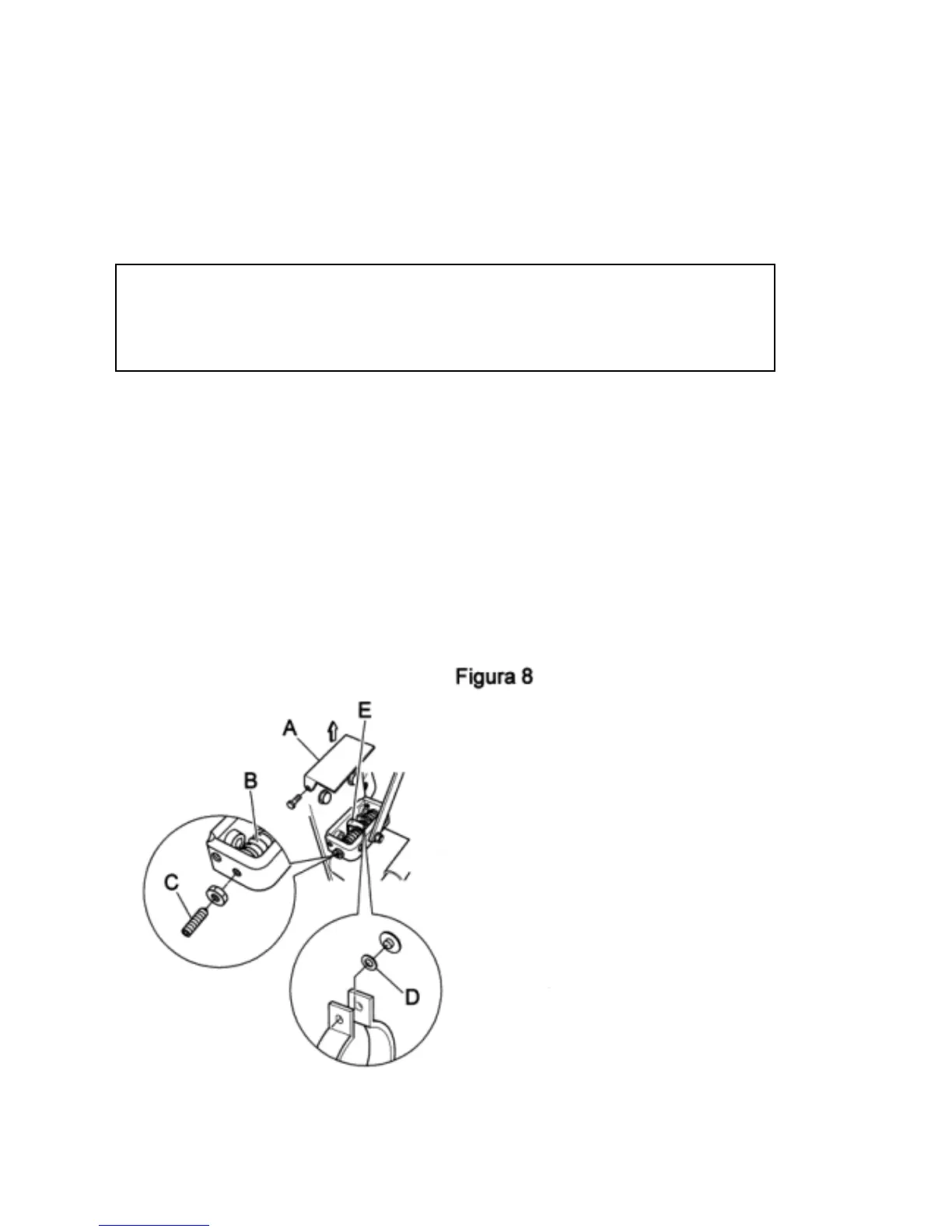
lows : - remove the cover (fig.8 ref. A),
-tighten both springs to the same load (fig. 8, ref. B) using the relative dowels (fig.
8, ref. C)
-check that the brake works properly. If the brake still does not work properly, the
brake lining may be worn, in which case the shims ( fig. 8, ref. D) must be re-
moved so that the eccentric control pin (fig. 8, ref. E) is slightly loose and not
locked into position.
Figure 8