- To access the transmission belts and rotor brake adjustment device area, re-
move the
plastic guard (fig. 9 ref. D) and unscrew and remove the 4 screws shown in fig-
ure 9 ref.A.
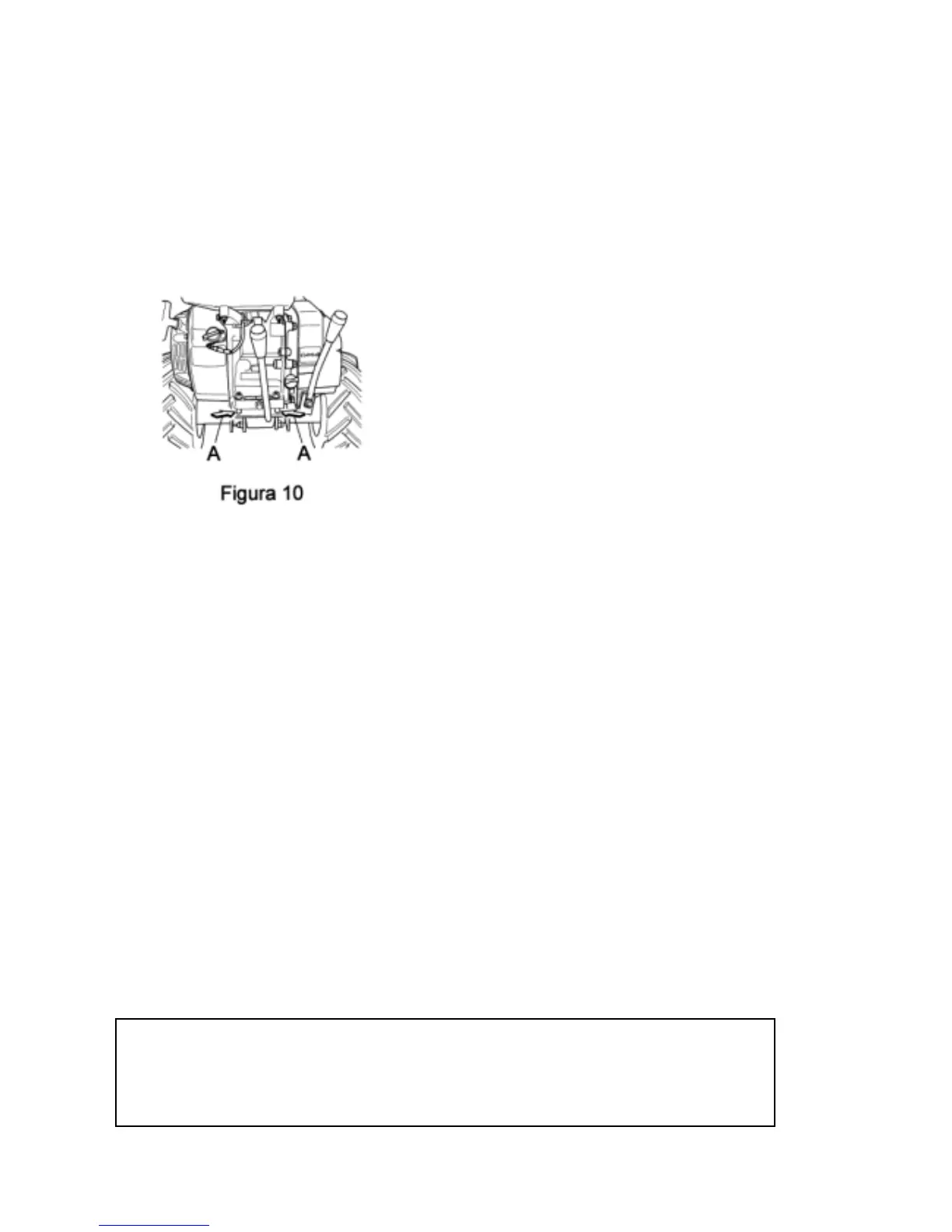
- Loosen the 4 screws that fix the engine to the chassis ( Fig. 10, ref. A)
Figure 10
- Move the engine slightly towards the rear of the machine (towards the han-
dlebars) until the belt shown in fig.11 (step 1) is in the ideal position. To
check the ideal work position, pinch the belt between your thumb and fore-
finger and make sure that the inside distance is about 38 mm.
- Make sure that the pulley ( fig. 11 ref. C) is correctly aligned with the pulley
in point D.
- Retighten the screws ( fig. 10 ref. A), and
proceed with the next adjustment phase ( step 2):
- pinch the belt shown in fig. 12 between your thumb and forefinger and
make sure that the inside distance is about 40 mm. If the inside distance is
less or more than 40 mm, use the pin shown in ref. A fig. 12a, loosening the
relative dowel (ref. B) by turning the pin clockwise or anticlockwise accord-
ing to adjustment requirements. Secure the dowel again once the ideal po-
sition has been reached.
- Proceed with the adjustment of the tightener ( ref. A in figure 12) using the
relative support pin and its dowel.
Then proceed with the next adjustment phase (step 3- fig. 13):
pinch the belt between your thumb and forefinger and make sure that the
inside distance is about 28 mm. If the inside distance is less or more than
28 mm, adjust the support between the engine and the rotor ( fig. 13a), by
first loosening the screws shown in fig. 13a and allowing the support to run
along the slots shown in refs. A and B of fig. 13a until the belt is in the ideal
position.
- Retighten the screws.
WARNING
After having made the replacements and adjustments as described above check
that the safety functions of flail rotor brake and the forward control brake work,
stopping roller and machine movement respectively. If not, adjust them following
the instructions given in section 14 B “CONTROL CABLE ADJUSTMENT