Preparing the equipment for use
ENGLISH 10
5. Preparing the equipment for use
5.1 Assembly of the guide bar and chain
The chain brake must be released
when assembling the chain and adjusting the
chain tension [pull back the hand protection (3)
to the front handle (4)].
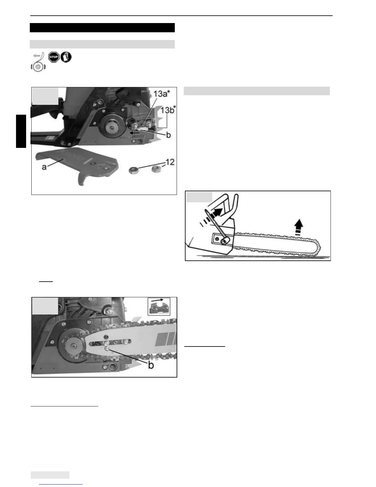
*13a ! 636, 642, 643IP; *13b ! 635
• Undo the retaining nuts on the rail cover (12).
• Take off the rail cover (a).
• When setting up the tool for the first time, remove
the cardboard disc inserted at the factory as
transport protection underneath the rail cover before
installing the guide bar.
• On used saws, clean the rail contact surface and the
oil outlet.
• Use the chain tensioning bolt (13a / 13b) to move
the chain tensioning cam (b) to the left-hand end
stop. .
Note:
Each time the guide bar is removed and
installed, adjust the chain tension cam (b) up to the
l.h. end stop.
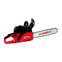
• Position the guide bar; in the process, the chain
tensioning cam (b) must fully engage in the
designated hole in the guide bar.
Notes for new saw chains:
Before installing a new chain
we recommend soaking it in a container (bowl) with
chain oil with anti-fling additives that help the oil adhere
to the chain.
• Fit the chain over the sprocket and into the guide
groove of the guide bar. The cutting elements of the
saw teeth must be on the upper side of the rail
facing towards the tip of the rail.
• Ensure that the drive links grip correctly between the
teeth of the chain wheel and reversing wheel at the
tip of the guide bar.
• Fit the rail cover, but initially only tighten the retaining
nuts finger tight.
• After correctly adjusting the chain tension (refer to
the next section), tighten the retaining nuts as
described below.
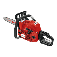
5.2 Adjusting the chain tension
• Loosen the retaining nuts on the rail cover (12), or if
you are assembling the chain, only tighten it finger-
tight.
• Place the rail tip on a suitable wooden support (e.g. a
tree stump) and press the guide bar upwards slightly
as a result.
• Use the chain tensioning bolt (13) to set the correct
chain tension. Turn the chain tensioning bolt
clockwise to increase the chain tension or anti-
clockwise to slacken the chain tension. The chain
has the correct tension if it makes full contact with
the guide bar but can still be lifted off the guide bar
by hand by around 2 - 4 mm.
(schematic diagram)
• With the rail tip placed on a suitable surface and the
guide bar pressed up slightly, tighten the retaining
nuts with the enclosed combination tool. Then check
the chain tension again.
Always check the chain tension before starting the
device and adjust it as required. You should also check
the chain tension again and adjust it as required once
the power tool has warmed up and again intermittently
while working with the tool – but make sure the engine
is switched off first!
Important hint:
As the chain tightens again slightly when the device
cools off, slacken the chain tension a little once you
have finished work before putting the chainsaw into
storage.
Fig. 4
Fig. 2
(643IP)
Fig. 3
(643IP)