Operating and maintenance information
ENGLISH 17
11. Operating and maintenance information
With modern equipment and safety-relevant
components, maintenance and repairs must only be
carried out by persons with suitable specialist
qualifications in a workshop equipped with the
necessary special tool and testing equipment. As a
result, the manufacturer recommends that all work
which is not described in these operating instructions
should be performed by a specialist workshop. The
experts have access to the training, experience and
equipment which is required in order to provide you with
the most cost-effective solution. An expert can also
offer invaluable advice.
Always follow all of the safety instructions when
performing maintenance work.
After the device has been run in for around 5 operating
hours, all accessible nuts, bolts and screws (except the
carburettor adjusting screws) should be checked for
tightness and retightened as required.
It is best to store the device in a dry and safe location
with a full fuel tank. There must not be any naked
flames or similar nearby. If you plan to not use the
chainsaw for a longer period (i.e. more than four
weeks), please refer to the information in chapter 11.7
"Taking the chainsaw out of operation and putting it into
storage.
11.1 Maintenance and care of the cutting gear
Saw chain:
Just like any other cutting tool, the saw chain is subject
to natural wear. Your chainsaw will only be able to
deliver its full potential if the saw chain is correctly
sharpened. Every saw chain is matched to the relevant
chainsaw type in terms of its form, cutting performance
and design. Only use the genuine SOLO saw chain
which is approved for your chainsaw / guide bar type.
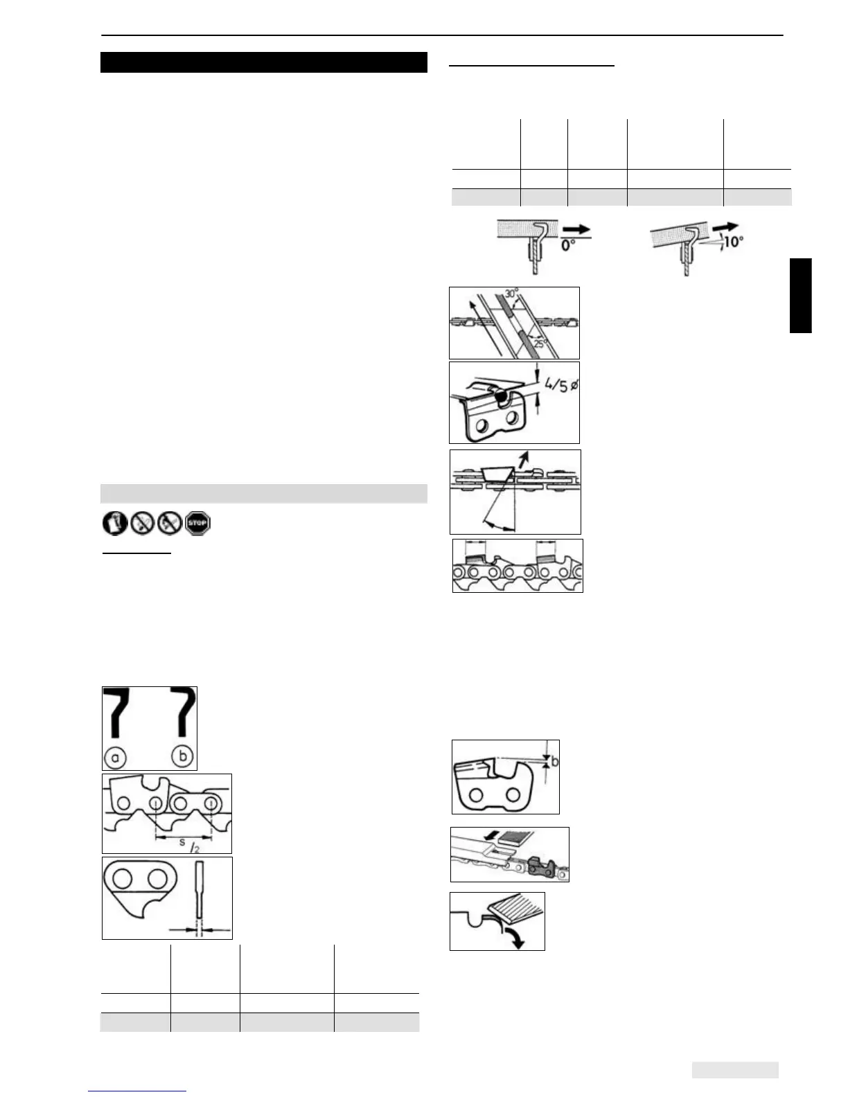
The key distinguishing factors for the saw chain are:
The form of the cutting elements,
a) Solid bit (rectangular cutting tooth,
professional chainsaws)
b) Half bit (half-round cutting tooth,
semi-professional / hobby chainsaws)
The pitch
This is the distance s (from one
rivet to the next but one) divided
by 2.
The pitch is quoted in inches
The driving link thickness
This is the thickness of the part
of the driving link which
protrudes in the guide groove of
the rail.
Pitch
in inches
in mm
Driving link
thickness in
mm
in inches
3/8’’ Spez. 9,32 mm 1,3 mm .050’’
.325’’ 8,25 mm 1,5 mm .058’’
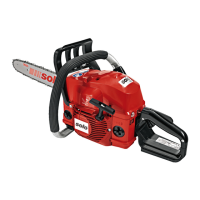
Sharpening the saw chain:
A special round chain file with the correct diameter
should be used for sharpening. Normal round files are
not suitable.
Pitch
in inches
Files Ø
mm/zoll
Filing
angle α
Depth limiter
spacing b
mm/zoll
Filing
direction
3/8’’ Spez.
4,0/
5
/
32
30° 0,64 / .025 0° horizon
.325’’(21BP) 4,8/
3
/
16
30° 0,64 / .025 10° upw.
A file holder makes guidance of
the file easier, as it has
markings for the correct
sharpening angle (align the
markings parallel to the saw
chain) and limits the penetration
depth (4/5 of the file diameter)
Position the file holder on the
roof of the tooth. The file should
only engage during the forward
stroke. Lift the file off when
moving it back.
The shortest cutting tooth is
sharpened first. The length of
this tooth is then the target size
for all the other teeth on the
saw chain. All of the cutting elements must have the
same length.
To start with, file all of the cutting elements on one side
from the inside outwards, then file all of the cutting
elements on the other side.
Always fully file out any damage from the side plate or
the roof of the tooth.
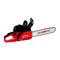
Correction of the depth limiter:
The distance b between the depth limiter (round nose)
and the cutting edge defines the
thickness of the chips. The best
cutting results are obtained with the
prescribed depth limiter spacing,
which should be checked every
time the saw chain is sharpened.
Lay the depth limiter gauge on the
cutting element. If the depth
limiter protrudes, file off the
protruding part with a flat file.
Round off the front edge of the depth
limiter. The original shape must be
restored. CAUTION: If the spacing is
too large then there is a greater risk of
kickback.
For your safety: If you would like to pull the chain
through while filing, pull the chain forwards with a
screwdriver towards the tip of the rail. This will reduce
the risk of slipping.