1
2
1
5
5
7
7
3
2
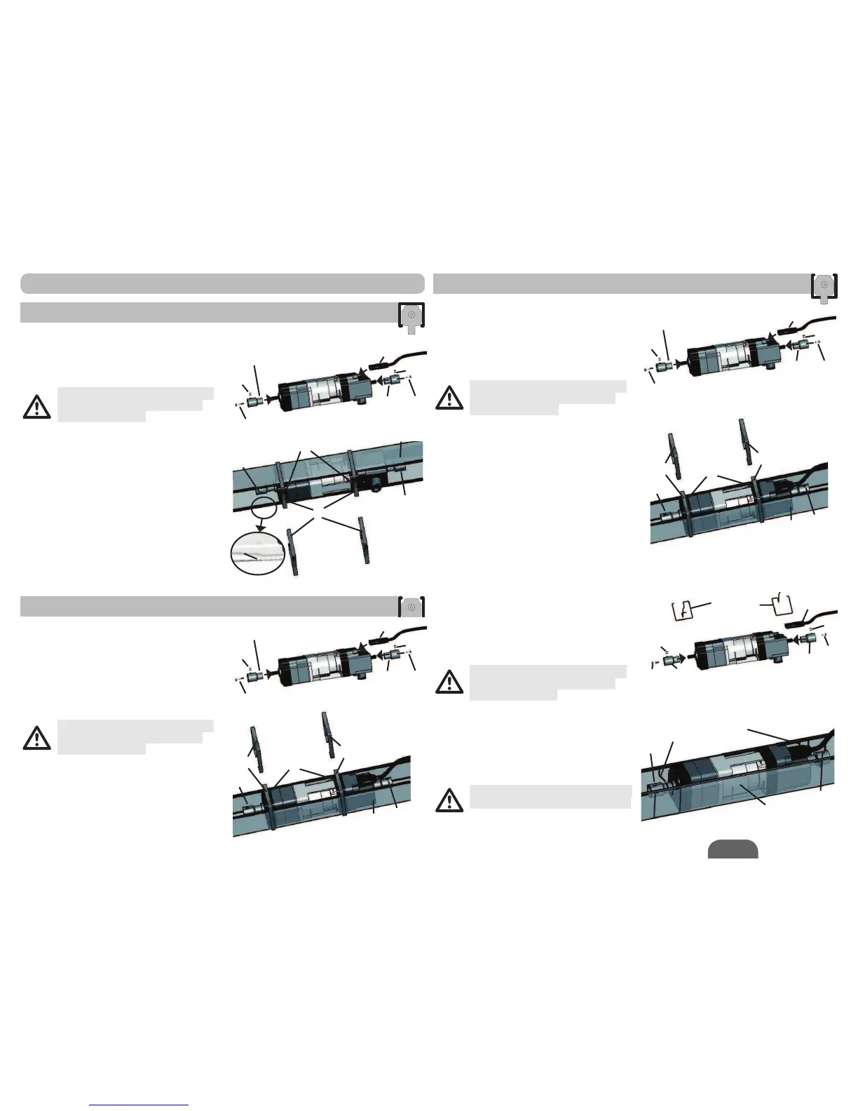
3.3.1. Assembly with external clips
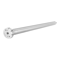
Fit the 2 adaptors (1) using 2 M3x8 screws (2)
on the motor shaft.
)Tightening torque = 1.1 N.m
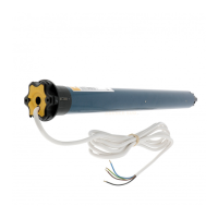
Connect the power supply cable (3) to the
motor.
Ensure that the cable does not hinder
the rotating part of the motor or the
Venetian mechanism.
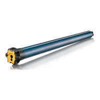
Insert the motor in the head rail (4).
Using the clips (5), fix the motor in the head
rail (4) on top of the small acoustic strips (6a).
The shaft can be fixed in the adaptor using a
grub screw (7).
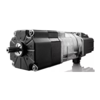
3.3.2. Assembly with internal clips
Fit the 2 adaptors (1) using 2 M3x8 screws (2)
on the motor shaft.
)Tightening torque = 1.1 N.m
Connect the power supply cable (3) to the
motor.
Ensure that the cable does not hinder
the rotating part of the motor or the
venetian mechanism.
Insert the motor in the head rail (4).
Using the clips (5), fix the motor in the head
rail (4).
The shaft can be fixed in the adaptor using a
grub screw (7).
Internal clips cannot be used with J418
motors (J4 motors with 18 N.m torque).
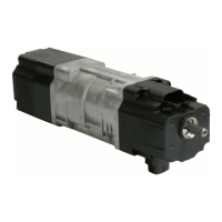
)LWWKHDGDSWRUVXVLQJ0[VFUHZV
on the motor shaft.
)Tightening torque = 1.1 N.m
Connect the power supply cable (3) to the
motor.
Ensure that the cable does not hinder
the rotating part of the motor or the
Venetian mechanism.
,IQHFHVVDU\3UHVVWKHHGJHRIWKHKHDGUDLO
(4) in the area of the motor.
Using the clips (5), fix the motor in the head
rail (4) on top of the small acoustic strips (6a).
The shaft can be fixed in the adaptor using a
grub screw (7).
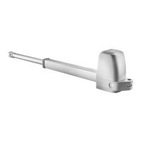
3.2.1. Assembly with external clips
Fit the 2 adaptors (1) using 2 M3x8 screws (2)
on the motor shaft.
)Tightening torque = 1.1 N.m
Connect the power supply cable (3) to the
motor.
Ensure that the cable does not hinder
the rotating part of the motor or the
Venetian mechanism.
Insert the motor in the head rail (4).
Using the clips (5), fix the motor in the head
rail (4) on top of the small acoustic strips (6a).
The shaft can be fixed in the adaptor using a
grub screw (7).