Do you have a question about the SOMFY SGS 200 and is the answer not in the manual?
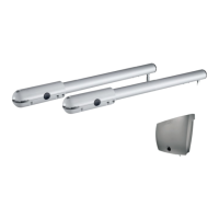
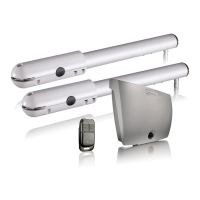
Steps for placing and attaching the switch box on the pillar, including drilling and mounting.
Details on connecting gate cylinders M1 and M2, including their specific terminal assignments.
Connect the antenna wire through a grommet for optimal functioning, avoiding cutting the wire.
Connect the power supply cable safely with power off, ensuring proper grounding and phase/neutral connections.
Procedure to memorize remote controls for total or pedestrian opening modes.
Switching remote control modes between 'opening total' and 'opening pedestrian or total'.
Process for memorizing gate leaf movement, forces, and stop angles for automatic operation.
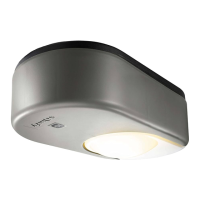
Mandatory safety devices for automatic mode: photo-electric cells, orange light, area lighting.
Setting up automatic mode where the gate closes by itself after passage, with a time delay.
Using sequential mode: total opening and pedestrian opening functions of the gate.
How the gate operates in automatic mode, including continuous opening and stopping.
Procedure to return from automatic mode to sequential mode using the remote control.
Steps to secure parametering by pushing buttons and cutting/restoring mains supply.
Procedure to reset and delete all recorded remote controls and parameters using the reset button.
Wiring diagrams and safety instructions for various sets of safety cells (e.g., 2400477, 2400599, 2400939).
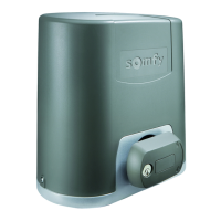
Function, connection, autonomy, charging, and lifespan of the backup battery (2400479).
Using an external antenna for longer range, its placement, and connection to the electronic box.
Explanation of indicator lights: orange light warning of motorization start-up.
| Max. gate leaf weight | 200 kg |
|---|---|
| Power supply | 230V AC |
| Motor voltage | 24V DC |
| Operating Temperature | -20°C to +55°C |
| Protection Class | IP44 |