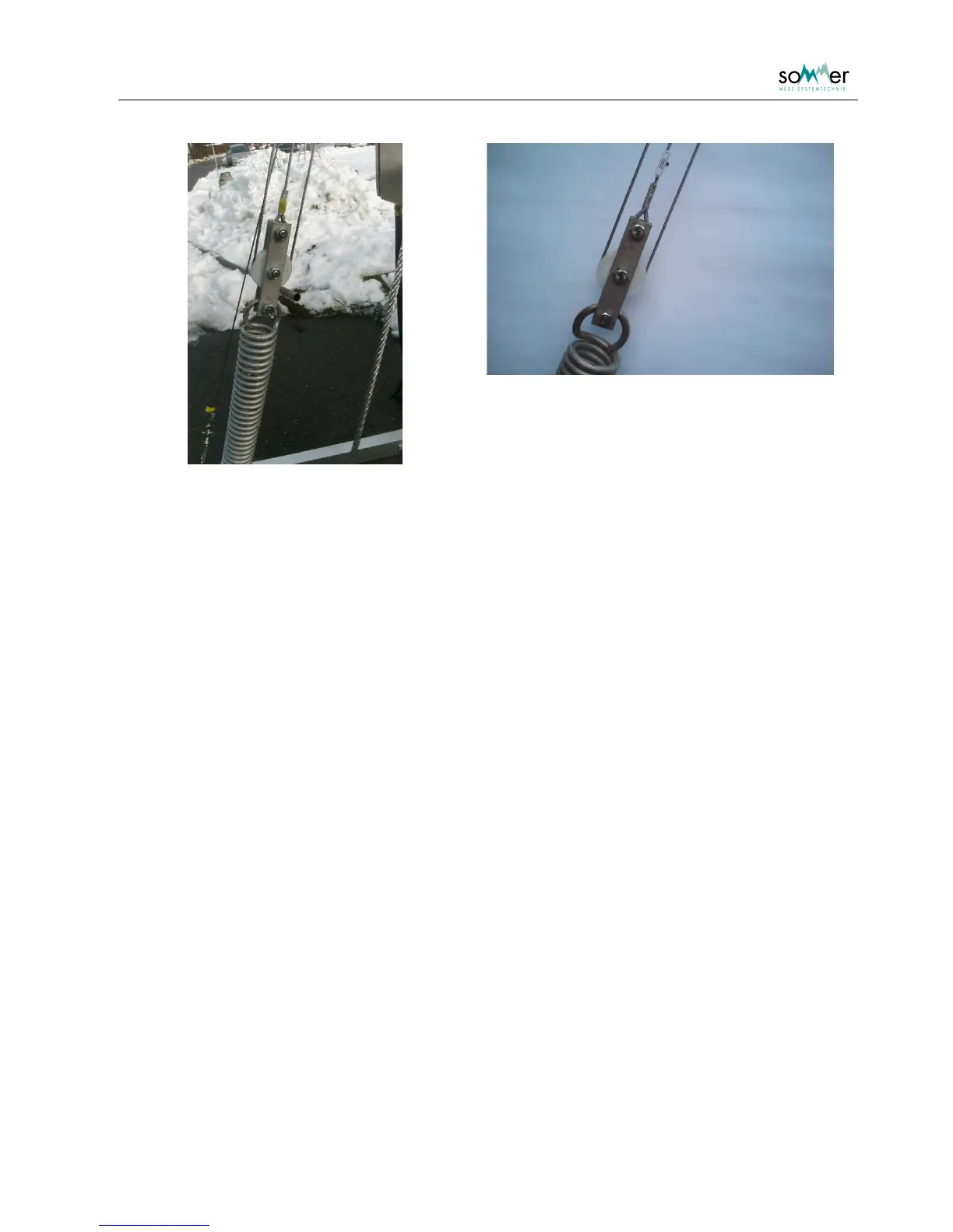
Fig. 10: Suspension at top of the spring with the pulley sytem (overview and detail)
The installation height of the sloping SPA-sensor should be higher than the maximum expected snow
depth. On the mast are three predrilled positions at heights of about 1.5, 2 and 2.5 m. Depending on the
selected height the L-shaped cross-beam is installed at the predefined positions at the far end of the
framework. The higher the sensor is spanned, the nearer the cross-beam is located, where the bottom
end of the SPA-sensor is fixed.
To span the sensor a spring and pulley system is used, that is spanned by a stretching device. The
stretching device is fixed at the near end of the framework and connected to the spring. The small bar with
the lower roll of the pulley system is connected to the opposite side of the spring. The rope of the pulley
system is fixed at the top screw of the bar connected to the spring. Then it is guided to the inner roll fixed
on the mast, back to the roll on the pulley system, up to the outer roll on the mast and through the roll of
the sensor. Finally it is connected to the screw located bellow the rolls on the mast. Then the sensor is
spanned using the stretching device.
3.5. Correction length sensor
If a correction length sensor (potentiometer) is used for the sloping sensor, it is installed at the deflector
roll located on the mast (Fig. 8). The bolt of the sensor has two rotary stop positions. Make sure that the
bolt is in the correct position to react to extensions of the suspension rope.