Do you have a question about the Sonardyne Lodestar and is the answer not in the manual?
Details regulations concerning the export of US Department of Commerce controlled items.
Provides an introduction to the manual's purpose and structure.
Describes the manual's purpose and scope.
Explains how the manual is structured into chapters and sections.
Identifies the intended audience for the document.
Provides an overview of the Lodestar system and its capabilities.
Provides an overview of the Lodestar system and its capabilities.
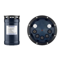
Details the controls and indicators on the surface unit's front panel.
Describes the connection ports on the subsea unit's end-cap.
Covers the procedures for starting up and shutting down the Lodestar.
Details the steps for powering on the Lodestar.
Details the steps for powering off the Lodestar.
Outlines the warranty terms and conditions for the Lodestar.
Introduces the technical specifications and lists available Lodestar models.
Introduces the specifications and lists available Lodestar models.
Introduces the technical specifications section.
Lists the available Lodestar models and their ratings.
Provides dimensional data and physical characteristics of the Lodestar.
Details electrical requirements and environmental operating conditions.
Details electrical power requirements and data interface specifications.
Details environmental operating conditions like ingress and temperature.
Outlines the performance metrics such as accuracy and speed.
Explains the importance of correct installation for performance.
Explains the importance of correct installation for performance.
Guides on handling and checking the unit upon receipt.
Lists factors for selecting an optimal installation site.
Covers the necessary steps for preparing the mounting location.
Details how to align the Lodestar with the vessel's axes.
Describes the necessary cabling for connecting the Lodestar.
Explains how to connect to listening equipment using NMEA.
Introduces guidance for fault identification and support.
Introduces guidance for fault identification and support.
Outlines a recommended procedure for diagnosing system faults.
Provides a list of questions for detailed problem identification.
Details the information needed for effective technical support.
Explains how to perform a hardware reset on the unit.
Explains how to perform a hardware reset on the unit.
Describes how to reset the Lodestar to its default configuration.
Explains the process of upgrading Lodestar firmware using PC utility.
Explains the process of upgrading Lodestar firmware using PC utility.
Provides guidance on how to contact Sonardyne for assistance.
Provides guidance on how to contact Sonardyne for assistance.
Lists the 24-hour emergency contact number and hours.
Lists the locations of Sonardyne's global offices.
Details various cables for the surface Lodestar unit.
Details various cables for the surface Lodestar unit.
Diagram for surface console cable.
Diagram for surface console test cable.
Diagram for surface comms test cable.
Diagram for surface transceiver cable.
Diagram for surface transceiver test cable.
Details auxiliary and power cables.
Diagram for auxiliary Lemo cable.
Diagram for gyro power cable.
Details various cables for the subsea Lodestar unit.
Diagram for subsea console cable.
Diagram for subsea console test cable.
Diagram for subsea comms C1 cable.
Diagram for subsea comms C1 test cable.
Diagram for subsea ethernet tail cable.
Diagram for subsea ethernet cable.
Diagram for subsea transceiver cable.
Diagram for subsea transceiver test cable.
Illustrates the coordinate system used by the Lodestar.
Illustrates the coordinate system used by the Lodestar.
| Output Rate | Up to 200 Hz |
|---|---|
| Input Voltage | 9-36 VDC |
| Storage Temperature | -40°C to +70°C |
| Heading Accuracy | 0.1° |
| Depth Rating | 4000 m |
| Communication Interfaces | RS-232, Ethernet |