Lodestar Hardware
Manual
Document Ref: UM-8084-
Issue: A– Rev
© Sonardyne International Limited 201
TRANSCEIVER PORT AND DATA/LINK LEDS
The remaining LEDs show the status of the transceiver ports and the data port, as
explained in Table 3.
Table 3 – Transceiver and data LEDs
Illuminates when the Ethernet link is
active and is passing data.
Illuminates to show the Ethernet link
is available.
stud
The surface version has a safety grounding stud fixed to the front panel. It is
necessary to connect this to a good grounding point on the vessel. This connection
is in addition to the ground connection made through the cable.
The Surface Lodestar must be permanently bonded to a
suitable grounding point on the vessel using the grounding stud.
16 AWG cable (or better) should be used for this.
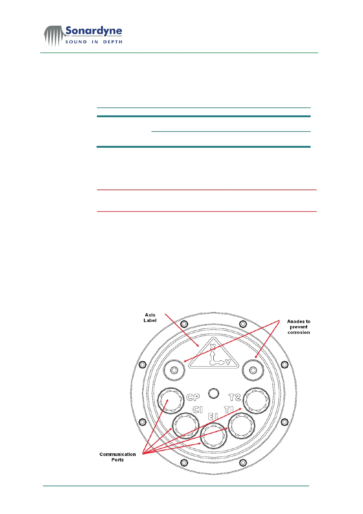
3.3 Connectors of the Subsea Lodestar
The subsea version of the Lodestar AHRS does not include any operator controls
or indicators. The unit’s housing is cylindrical with two end-
watertight seals of the appropriate depth rating.
One end-cap is flat to support mounting against a flat surface. The other end-cap
includes ports for connection between L
odestar and external equipment and
supplies. The Subsea Lodestar is shown in Figure 2.
Figure 2 – Subsea Lodestar – End-cap Connections