9
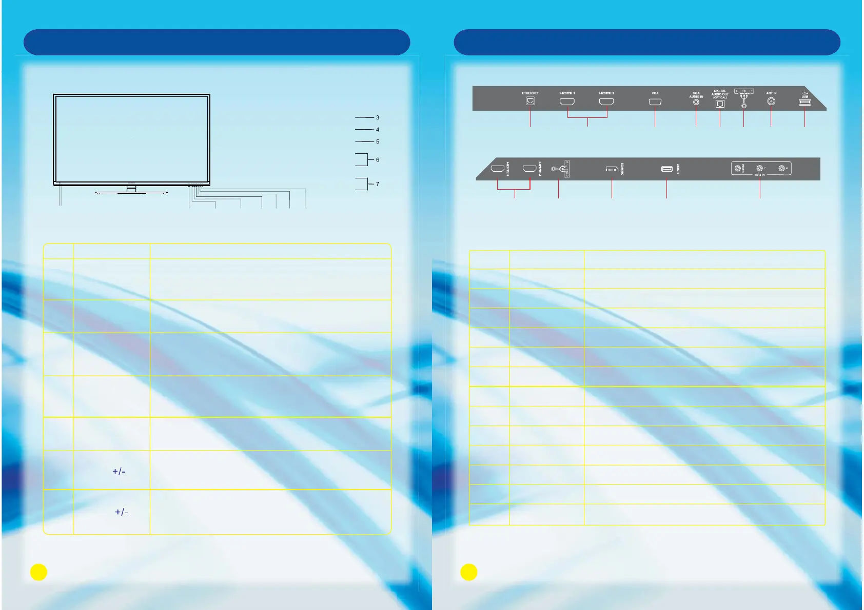
Front Panel
Main Unit Control
10
Main Unit Control
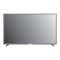
Rear Panel
1
2
3
4
5 6
7
8
9
10
11 12 13
No.
1
2
3
4
5
6
7
8
9
10
11
12
13
ANT IN
USB
AV IN
USB 3.0
ETHERNET
HDMI1/HDMI2
VGA
VGA AUDIO IN
Connect it to the home network.
Connect the HDMI cable.
Connect the PC VGA cable of your personal computer.
DVI or PC VGA audio input.
Connect to external antenna.
Connect USB device, such as USB disk, HID and so on.
Connect the audio and video output of your AV equipment to the unit.
Connect for media files playback and program recording.
Not compatible with USB1.1.
Name Description
DIGITAL AUDIO OUT
OPTICAL
Connect the OPTICAL to the Audio Amplifier using an optical cable.
COMPONENT IN
Connect the component video signal.
HDMI3/HDMI4
Connect the HDMI signal.
R-L-VIDEO VIDEO 1 IN
Connect the audio and video output of your AV equipment to the unit
using the AV cable included in the spare part.
SD/MMC
SD/MMC card reader slot.
STANDBY
MENU
SOURCE
CH+
CH-
VOL+
VOL-
VOL+
VOL-
CH-CH+
SOURCE
MENU
STANDBY
12
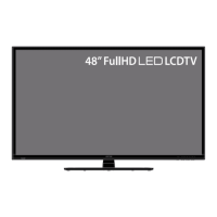
Front View
No.
1
2
5
Name
Remote Control
Sensor Window
Power Indicator
Description
Receives the signal from the Remote Control. Do not
put any objects in front of the window in order not to
hinder the reception of signal.
Flashes red when the unit is powered on:
Lights up red when the unit is in standby mode.
Press to display all possible input signal sources.
Press to cycle through various sources.
SOURCE
4
Press this button to display the OSD menu.
When the OSD menu is on, press this button to exit the
menu.
MENU
3
Press this button to turn the unit on when it is in standby
mode.
Press this button once more to put it to standby mode.
STANDBY
7
Press VOL + to increase volume, or VOL - to decrease.
At the OSD menu, press these buttons to move the
selection focus left and right to change settings.
VOL
6
Press these buttons to sequentially select channels.
When the OSD menu is on, press these buttons to
move the selection focus up or down to change settings.
CH