Grill Assembly
10
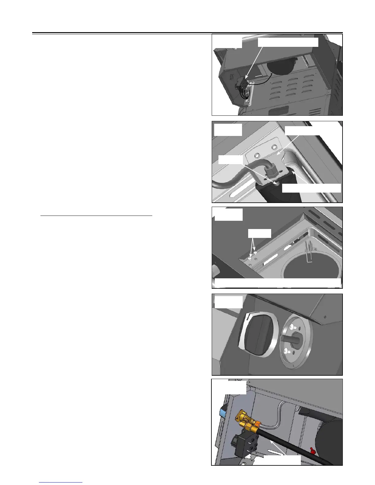
Fig. 9
Fig. 10
6 pole igniter module
Orice bracket
side burner bracket
Orice
4. Connect loose igniter wires from the grill to the
open terminals of the igniter. (See Fig. 9)
Note: The igniter is designed in such a way that
it does not matter which terminal tab is used
when connecting igniter wires.
5. Remove the two Phillips pan head M5 x 10 screws
from the orifice bracket. Align the orifice into the
center of the side burner bracket. (See Fig. 10)
SIDE BURNER PARTS ASSEMBLY
6. Use two screws removed in step 5 to secure the
orice backet on the side burner tray. (See Fig. 11)
Note: Add lock washer when installing the screws in
position.
7. Remove the two screws from the side burner valve
assembly. Slide the side burner valve stem through
the center hole in the front of the shelf. Insert one
valve screw through the bezel and into the side
burner valve and tighten. Next, install the second
valve screw through the bezel and tighten. Make
sure the bezel is installed with the "OFF" position
facing up. Install control knob, making sure to line
up the at side of the valve stem with the at side
of the knob stem. (See Fig. 12)
WARNING
:
When you install the side burner valve,
make sure the black tube is located under the
valve. (See Fig. 12a)
Fig. 11
Screws
Orice bracket underneath the side burner tray
Fig. 12
Fig. 12a
Black tube