Sony 7700 (Y2K) 17/03/00
Page 3 of 8
Installation
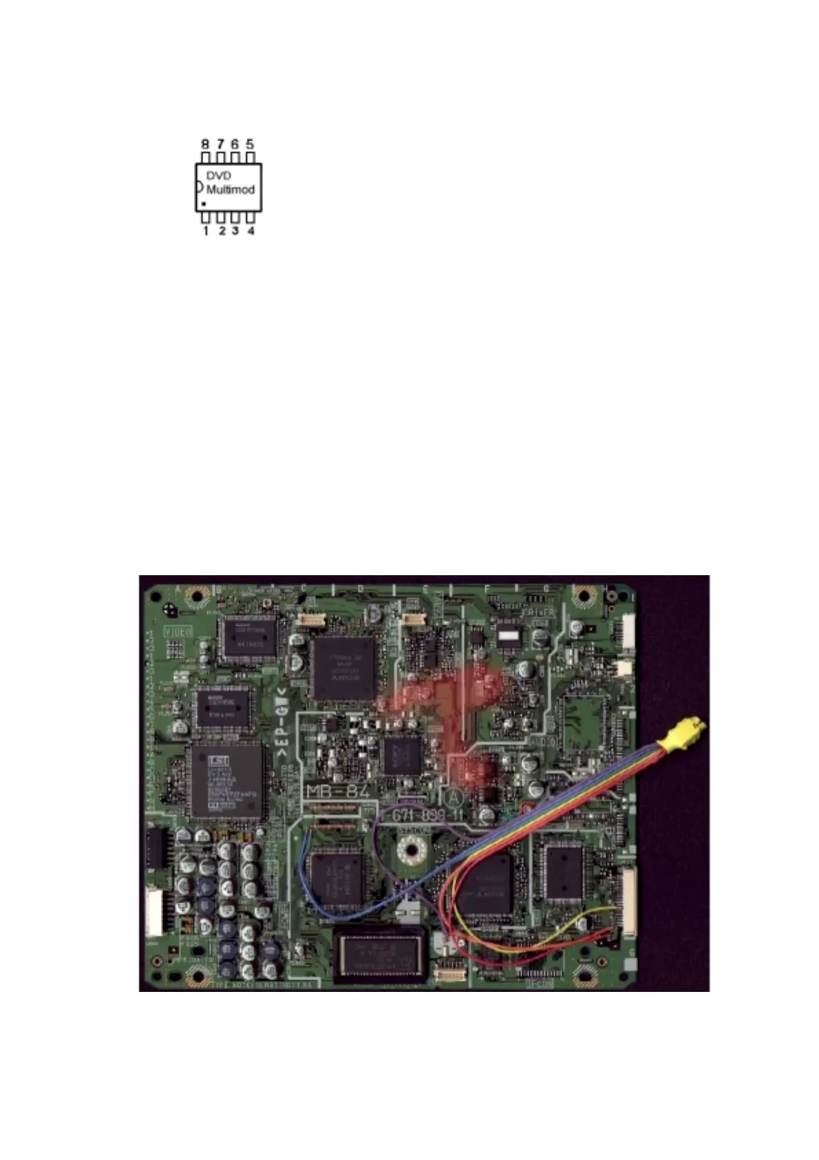
• The chip has 8 pins.
• Pin 1 - CN601 Pin 1 (Red)
• Pin 3 - CN601 Pin 2 behind the capacitor (Orange)
• Pin 4 - CN601 Pin 8 (Yellow)
• Pin 5 - CN803 next to the MB84 inscription / soldering point in the middle of the
triple solder pads / Pin 70 on Main PCB (Green)
• Pin 6 - CN803 next to the MB84 inscription / soldering point to the left of the triple
solder pads. (Blue)
• Pin 8 – Soldering point to the middle of the MB84 print of capacitor 866 next to
ICS803 (Purple)
• Colours correspond to the colours used in Figure 1
• Replace firmware with the 44 pin TSOP chip.
Figure 1 (below) Overview of connections