– 14 –
SECTION 4
ELECTRICAL ADJUSTMENTS
Note:
1. CD block is basically designed to operate without adjustment.
Therefore, check each item in order given.
2. Use YEDS-18 disc (Part No.: 3-702-101-01) unless otherwise
indicated.
3. Use the oscilloscope with more than 10 MΩ impedance.
4. Clean an object lens by an applicator with netural detegeent
when the signal level is low than specified value with the fol-
lowing checks.
S-Curve Check
Connection
Procedure:
1. Connect an oscilloscope to TP5 (FE: IC107 !∞ pin) on SERVO
board.
2. Connect TP4 (FEI: IC105 @ª pin) and TP (VC: CN108 2
pin) on Servo board with a lead wire.
3. With the disc (YEDS-18) loaded, turn ON the POWER switch
to execute focus searching.
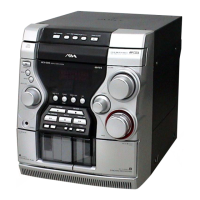
4. In such a case, confirm the symmetry and level (p-p value) of
the waveform (S-curve) on the oscilloscope.
S-curve waveform
5. After check, remove the lead wire connected in step 2.
Note: • Try to measure several times to make sure that the ratio
of A: B or B: A is more than 10: 7.
• Take sweep time as long as possible and light up the
brightness to obtain best waveform
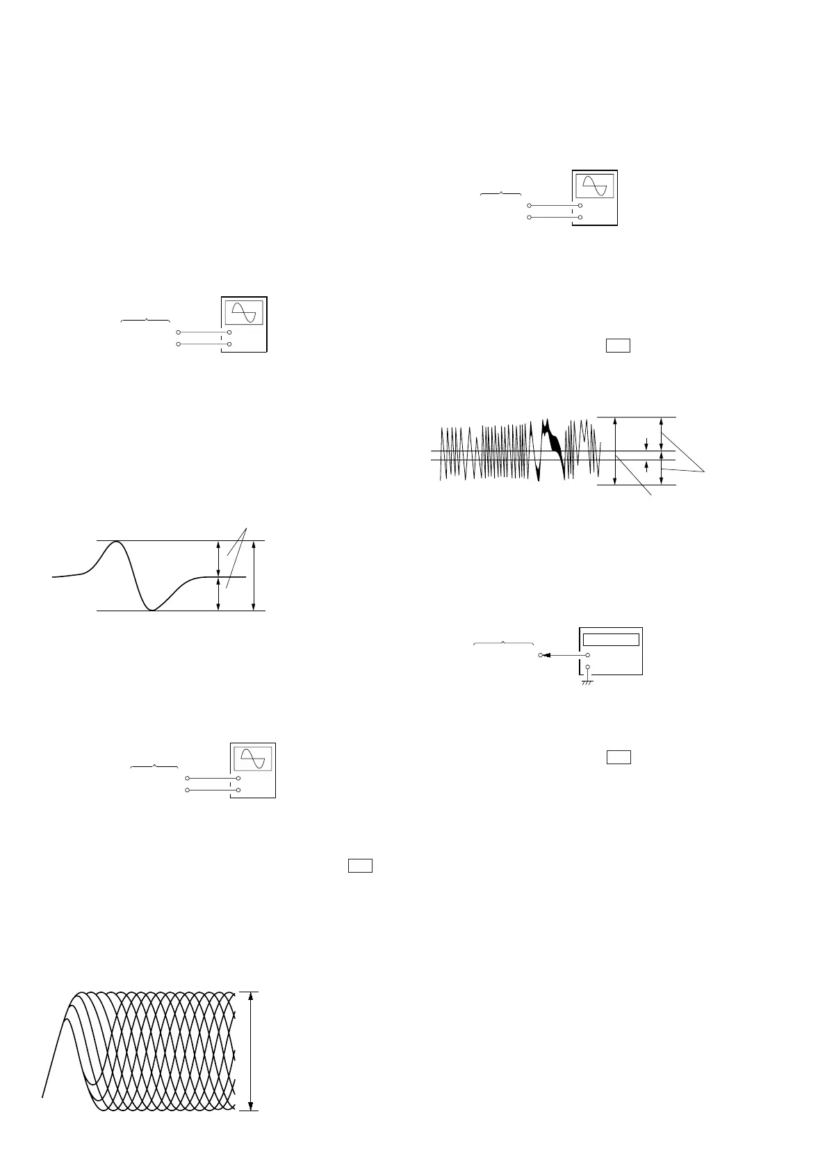
RF Level Check
Connection:
Procedure:
1. Connect an oscilloscope to the TP (RFO: CN108 3 pin)
2. Turn ON the POWER switch.
3. Load the disc (YEDS-18), and play the 5th music with ·
(PLAY) and AMS Keys.
4. Confirm that a waveform and RF level on the oscilloscope are
proper.
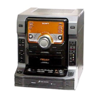
Note: Clear RF signal waveform means that the shape “≈” can
be clearly distinguished at the center of the waveform.
RF signal waveform
VOLT/DIV: 200 mV
TIME/DIV: 500 ns
(with the 10 : 1 probe
in use)
level: 1.2 Vp-p
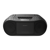
E-F Balance (Traverse) Check
Connection:
Procedure:
1. Connect TP (ADJ: CN105 3 pin) on Servo Board to GND,
and TP3 (TEI: IC105 @¶ pin) to TP (VC: CN108 2 pin) with
lead wires respectively.
2. Connect on oscilloscope to TP (TE: CN108 1 pin).
3. Turn ON the POWER switch.
4. Load the disc (YEDS-18) and press · (PLAY) button.
5. Confirm that a waveform on oscilloscope is vertically sym-
metric to A[Vdc], and also its level is proper.
Traverse waveform
+
–
SERVO board
TP (RFO)
TP (VC)
oscilloscope
(AC range)
+
–
SERVO board
TP (TE)
TP (VC)
oscilloscope
(DC range)
0Vdc
B
A
symmetric
level: 1.3 ± 0.6 Vp-p
At this time, A/B × 100 = ± 22 (%) or less
6. After check, remove the lead wire connected in step 1.
RF PLL Free-run Frequency Check
1. Connect a frequency counter to the TP (XPLCK: CN106 1
pin).
2. Turn ON the POWER switch.
3. Load the disc (YEDS-18) and press · (PLAY) button.
Confirm that the frequency at TP (XPLCK) is 4.3218MHz.
FOCUS/TRACKING AUTO GAIN DATA SETTING
Refer to 1-1. Writing focus/tracking auto gain data on page 3.
+
–
Frequency counter
SERVO board
TP (XPLCK)
+0.25
–0.20
+
–
SERVO board
TP5 (FE)
TP (VC)
oscilloscope
within 3.0 ± 1.0 Vp-p
A
B
symmetric