– 52 –– 51 –
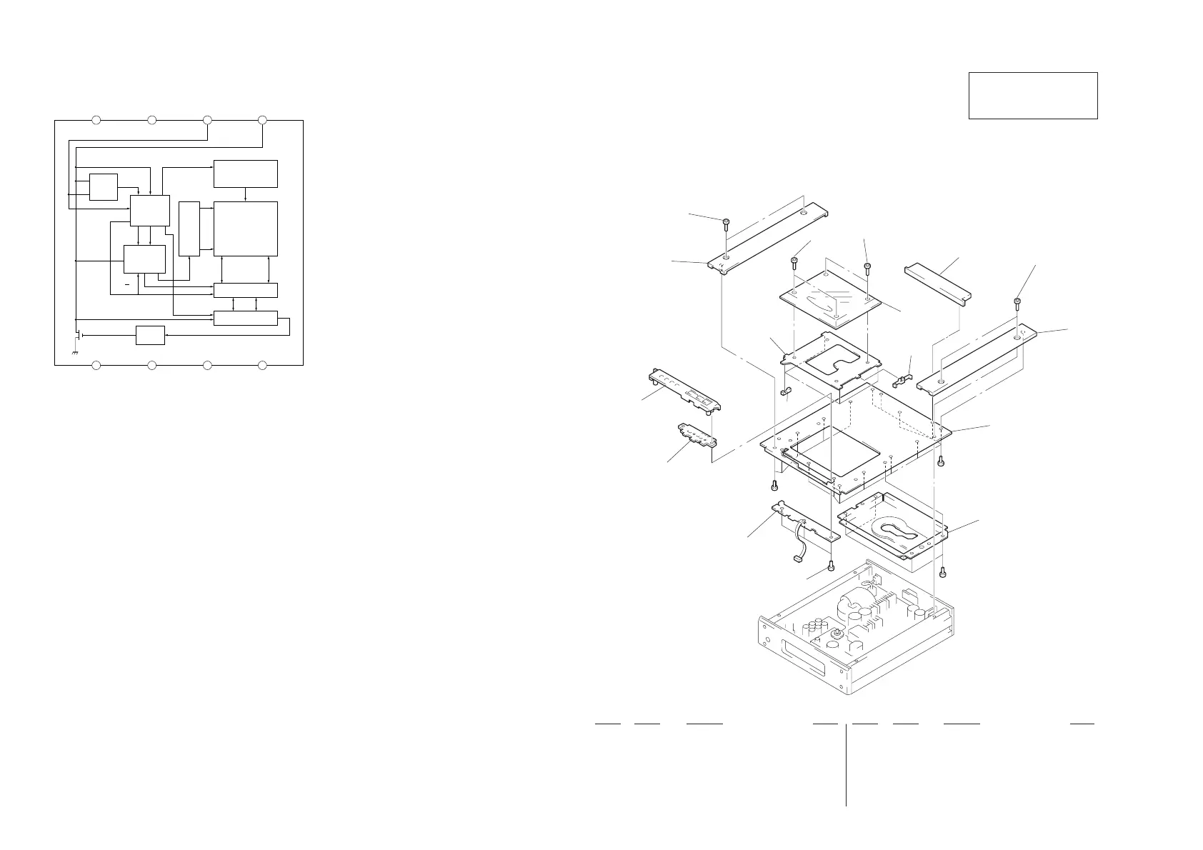
– CONTROL Section –
IC803 X24C01S
8
VCC
7
TEST INPUT
6
SCL
5
SDA
1
NC
2
NC
3
NC
4
VSS
START
STOP
LOGIC
CONTROL
LOGIC
START CYCLE
H.V. GENERATION
TIMING
& CONTROL
E PROM
32 x 32
2
32
XDEC
INC
LOAD
5
R/W
PIN
2
8
D
OUT
CK
32
WORD
ADDRESS
COUNTER
YDEC
D
OUT
ACK
DATA REGISTER
SECTION 6
EXPLODED VIEWS
(1) TOP PLATE SECTION
1
2
3
4
5
6
7
14
7
8
9
14
6
11
10
12
13
#1
#1
#2
Ref. No. Part No. Description Remark Ref. No. Part No. Description Remark
* 1 A-4699-306-A KEY BOARD, COMPLETE
2 4-988-644-01 SHEET (LED)
3 X-4947-750-1 PANEL (PLAY) ASSY
4 4-979-030-01 SLIDER
5 4-979-039-01 HOLDER (R)
* 6 4-986-468-01 PANEL (TOP)
7 4-960-910-21 SCREW, ORNAMENTAL (M3X8)
8 4-979-028-01 WINDOW, DISK
* 9 4-986-477-01 PANEL (STOP)
10 4-979-045-01 SLIDER (B)
* 11 4-986-467-01 BRACKET (TOP)
* 12 4-986-479-01 BRACKET (BU)
13 4-951-620-01 SCREW (2.6X8), +BVTP
14 4-960-910-11 SCREW, ORNAMENTAL
The components identified by mark
! or dotted line with mark ! are
critical for safety.
Replace only with part number
specified.
• Items marked “*” are not stocked since they
are seldom required for routine service. Some
delay should be anticipated when ordering
these items.
• The mechanical parts with no reference num-
ber in the exploded views are not supplied.
• Hardware (# mark) list is given in the last of
the electrical parts list.
NOTE:
• -XX and -X mean standardized parts, so they
may have some difference from the original
one.
• Color Indication of Appearrance Parts
Example:
KNOB, BALANCE (WHITE) . . . (RED)
↑↑
Parts Color Cabinet's Color