CDX-GT35U/GT39U/GT39UE
4
SECTION 1
SERVICE NOTE
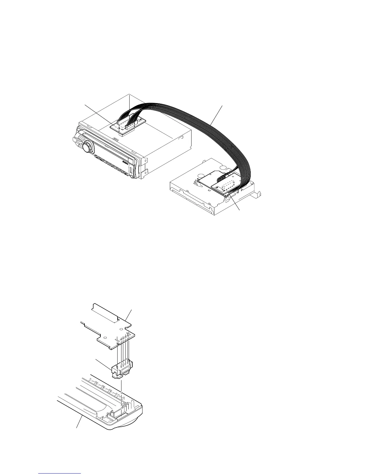
EXTENSION CABLE AND SERVICE POSITION
When repairing or servicing this set, connect the jig (extension
cable) as shown below.
• Connect the MAIN board (CN701) and the SERVO board
(CN401) with the extension cable (Part No. J-2502-076-1).
NOTE FOR REPLACEMENT OF THE SERVO BOARD
When repairing, the complete SERVO board (Part No.
A-1555-002-A) should be replaced since any parts in the SERVO
board cannot be repaired.
NOTE FOR REPLACEMENT OF THE USB CONNECTOR
(CN902)
To replace the USB connector requires alignment.
1. Insert the USB connector into the front panel.
2. Place the KEY board on the front panel and align the terminals
of the USB connector with the holes in the KEY board.
3. Solder the four terminals of the connector.
NOTE FOR THE 20-PIN CONNECTOR (CN901)
Do not use alcohol to clean the 20-pin connector (CN901) connect-
ing the front panel with the main body.
Do not touch the connector directly with your bare hand. Poor con-
tact may be caused.
SERVO BOARD
CN401
MAIN BOARD
CN701
J-2502-076-1
KEY board
front panel
USB (socket) connector
 Loading...