EasyManua.ls Logo

Sony CFD-G500 Service Manual

Sony CFD-G500
56 pages
To Next Page IconTo Next Page
Page #1 background imageLoading...
Page #1 background image
SERVICE MANUAL
Sony Corporation
Personal Audio Division
Published by Sony Engineering Corporation
US Model
Canadian Model
E Model
Australian Model
CFD-G500
AEP Model
CFD-G500/G500L
UK Model
CFD-G500L
CD RADIO CASSETTE-CORDER
9-877-730-05
2005J16-1
© 2005.10
Ver. 1.4 2005.10
SPECIFICATIONS
CFD-G500/G500L
Model Name Using Similar Mechanism CFD-S250L
CD
CD Mechanism Type KSM-213RDP/KSM-213CDP
Section
Optical Pick-up Type KSS-213R/KSS-213C
TAPE
Model Name Using Similar Mechanism CFD-S250L
Section
Tape Transport Mechanism Type MF-G500
CD player section
System
Compact disc digital audio system
Laser diode properties
Material: GaAlAs
Wave length: 780 nm
Emission duration: Continuous
Laser output: Less than 44.6 µW
(This output is the value measured at a distance
of about 200 mm from the objective lens surface
on the optical pick-up block with 7 mm
aperture.)
Spindle speed
200 r/min (rpm) to 500 r/min (rpm)
(CLV)
Number of channels
2
Frequency response
20 - 20 000 Hz +1/–2 dB
Wow and flutter
Below measurable limit
Radio section
Frequency range
CFD-G500
FM 87.5 - 108 MHz
AM 531 - 1 611 kHz
CFD-G500L
FM 87.5 - 108 MHz
MW 531 - 1 611 kHz (9 kHz step)
530 - 1 610 kHz (10 kHz step)
LW 153 - 279 kHz
IF
FM: 10.7 MHz
AM/MW/LW: 450 kHz
Aerials
FM: Telescopic aerial
AM/MW/LW: Built-in ferrite bar aerial
Cassette-corder section
Recording system
4-track 2 channel stereo
Fast winding time
Approx. 120 s (sec.) with Sony cassette C-60
Frequency response
TYPE I (normal): 70 - 13 000 Hz
General
Speaker
Full range: 10 cm dia., 3.2 , cone type (2)
Woofer: 10 cm dia., 4 , cone type (1)
Input
LINE IN jack (stereo minijack):
Minimum input level 330 mV
Output
Headphones jack (stereo minijack)
For 16 - 68 impedance headphones
Maximum power output
Full range: 8 W
Woofer: 12 W
Power requirements
For CD radio cassette-corder:
230V AC, 50 Hz
12 V DC, 8 R20 (size D) batteries
For remote control:
3 V DC, 2 R03 (size AAA) batteries
Power consumption
AC 30 W
Battery life
For CD radio cassette-corder:
FM recording
Sony R20P: approx. 6 h
Sony alkaline LR20: approx. 18 h
Tape playback
Sony R20P: approx. 1.5 h
Sony alkaline LR20: approx. 6 h
CD playback
Sony R20P: approx. 1 h
Sony alkaline LR20: approx. 4 h
Dimensions
Approx. 530 × 327 × 241 mm (w/h/d)
(incl. projecting parts)
Mass
Approx. 8 kg (incl. batteries)
Supplied accessory
Mains lead (1)
Remote control (1)
Design and specifications are subject to change
without notice.
Photo : CFD-G500

Other manuals for Sony CFD-G500

Question and Answer IconNeed help?

Do you have a question about the Sony CFD-G500 and is the answer not in the manual?

Sony CFD-G500 Specifications

General IconGeneral
BrandSony
ModelCFD-G500
CategoryCD Player
LanguageEnglish

Summary

Specifications

Section 1 Servicing Notes

Safety Check-out

Procedures for checking safety after service, focusing on AC leakage and general safety compliance.

Leakage Test

Methods for measuring AC leakage current from exposed metal parts to earth ground.

Notes on Handling the Optical Pick-up Block or Base Unit

Precautions for handling the optical pick-up block to prevent electrostatic breakdown and damage.

Notes on Laser Diode Emission Check

Guidelines for safely checking laser diode emission from the optical pick-up block.

Chuck Plate Jig on Repairing

Information about using a specific jig for CD section repairs when the CD lid is open.

Laser Diode and Focus Search Operation Check

Steps to check laser diode emission and focus search operation in the CD section.

Section 2 General

Location of Controls

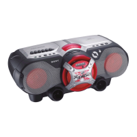
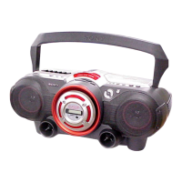
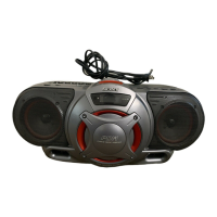
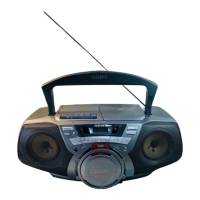
Diagrams and labels showing the location of all controls on the main unit.

Remote Control

Diagram and labels for the buttons and functions of the remote control.

Section 3 Disassembly

3-1. Cabinet (Upper) Section-1

Procedure for disassembling the first part of the upper cabinet.

3-2. Cabinet (Upper) Section-2

Procedure for disassembling the second part of the upper cabinet, including connector details.

3-3. Cabinet (Front) Section

Procedure for disassembling the front cabinet section.

3-4. Control 2 Board, Control 3 Board

Steps to remove the control boards, including screw and button removal.

3-5. LCD Board

Procedure for removing the LCD board and its associated flexible flat cable.

3-6. Power Board, Trans Board

Steps for removing the power and trans boards, including connector and harness disconnections.

3-7. Control 1 Board

Procedure for removing the control 1 board, including screws and buttons.

3-8. H/P Board, Tuner Board

Steps for removing the headphone/tuner boards, including soldering and connector removal.

3-9. Main Board

Procedure for removing the main board, including harnesses and flexible flat cables.

3-10. CD Block Section

Procedure for removing the CD block section, including screws.

3-11. Tape Mechanism Deck

Steps for removing the tape mechanism deck, including connectors and flexible flat cables.

3-12. TC Board

Procedure for removing the TC board, including soldering points and hooks.

3-13. Main Belt, Sub Belt

Steps for replacing the main and sub belts, including motor and pulley removal.

Section 4 Mechanical Adjustments

Tape Section

Details for adjusting tape section output level and standard output level.

Tape Speed Adjustment Procedure

Steps to adjust tape speed using a test tape and frequency counter.

Section 5 Electrical Adjustments

Tuner Section

AM Section

Procedures for adjusting AM IF, frequency coverage, and tracking.

FM Section

Procedures for adjusting FM IF, frequency coverage, and tracking.

CD Section

Focus Bias Check

Procedure to check focus bias using an oscilloscope and specific test disc.

Section 6 Diagrams

Circuit Boards Location

Diagram showing the physical location of all circuit boards within the unit.

6-1. Block Diagrams Main Section

- Tuner/CD Section

6-2. Printed Wiring Board CD Section

6-3. Schematic Diagram CD Section

6-4. Printed Wiring Board -Tuner Section (AEP, UK, CET Model)

6-5. Schematic Diagram Tuner Section (AEP, UK, CET Model)

6-6. Printed Wiring Board - Tuner Section (US, CND, E, SP, AUS Model)

6-7. Schematic Diagram Tuner Section (US, CND, E, SP, AUS Model)

6-8. Printed Wiring Board - TC Section

6-9. Schematic Diagram - TC Section

6-10. Printed Wiring Board - Main Section

6-11. Schematic Diagram - Main Section (1/2)

6-12. Schematic Diagram Main Section (2/2)

6-13. Printed Wiring Board - LCD Section

6-14. Printed Wiring Board Power Section

6-15. Schematic Diagram - Power Section

IC Block Diagrams

IC Pin Function Description

Section 7 Exploded Views

7-1. Overall Section

Exploded view of the overall unit, showing major external assemblies and parts.

7-2. Cabinet (Front) Section

Exploded view of the front cabinet section, detailing its components and assembly.

7-3. Cabinet (Rear) Section

Exploded view of the rear cabinet section, showing chassis, boards, and transformer parts.

7-4. Cabinet (Upper) Section-1

Exploded view of the first part of the upper cabinet, detailing buttons, boards, and screws.

7-5. Cabinet (Upper) Section-2

Exploded view of the second part of the upper cabinet, showing boards, cables, and screws.

7-6. Tape Mechanism Deck Section

Exploded view of the tape mechanism deck, including belts, motor, and chassis.

Section 8 Electrical Parts List

Resistors

List of resistors used in various sections, including their part numbers and specifications.

Capacitors

List of capacitors used in various sections, including their part numbers and specifications.

Semiconductors

List of semiconductors (diodes, transistors, ICs) with part numbers and locations.

Connectors

List of connectors with part numbers and pin configurations.

Switches

List of switches used in the unit, with their part numbers and functions.

Accessories

List of accessories supplied with the unit.

Supplement-1

Identification

Identification details for the KSM-213RDP and KSM-213CDP optical pick-up blocks.

Optical Pick-up Section (KSM-213RDP)

Optical Pick-up Section (KSM-213CDP)

Revision History

Related product manuals