– 14 –
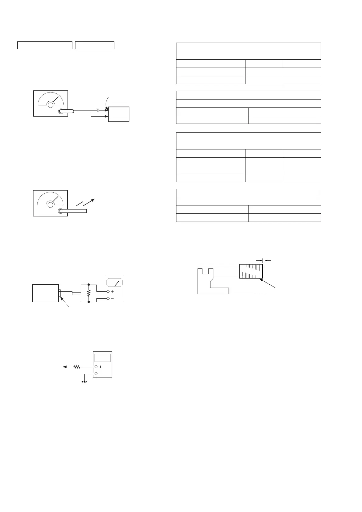
FM FREQUENCY COVERAGE
ADJUSTMENT
Frequency Display 87.5 MHz 108 MHz
Reading on Digital voltmeter 1.7 ± 0.4 V 4.1 ± 0.1V
Adjustment Part <confirmation> L2
FM TRACKING ADJUSTMENT
Adjust for a maximum reading on level meter.
L1 CT1
87.5 MHz 108 MHz
AM FREQUENCY COVERAGE
ADJUSTMENT
Frequency Display 530 kHz 1,710 kHz
Reading on Digital voltmeter 0.9
+ 0.7 V
4.8
+ 1.2V
– 0.5 V – 0.6 V
Adjustment Part <confirmation> <confirmation>
AM TRACKING ADJUSTMENT
Adjust for a maximum reading on level meter.
L4 CT3
620 kHz 1,400 kHz
• For AM adjustment, fix the ferrite-rod antenna (L3) as shown
below and then perform tracking adjustment at L4 and CT3.
Lastly check the voltage.
digital
voltmeter
100 k
Ω
TP (VT)
(JW18)
phones jack
set
32
Ω
level meter
(range: 0.5–5 V ac
Put the lead-wire
antenna close to
the supplied AM
loop antenna.
AM RF signal
generator
TP (FM ANT)
FM RF signal
generator
0.01
µ
F
set
TUNER SECTION 0 dB = 1 µV
• FM Section
Setting:
BAND switch: FM
75 kHz frequency
deviation by 1 kHz signal
output level : as low as possible
• AM Section
Setting:
BAND switch: AM
30% amplitude
modulation by
400 Hz signal
• Connecting Level Meter (FM and AM)
• Connecting Digital Voltmeter (FM and AM)
• Repeat the procedures in each adjustment several times, and the
frequency coverage and tracking adjustments should be finally
done by the trimmer capacitors.
3.0
±
1.0 mm
L3
FERRITE-ROD
ANTENNA
Adjustment Location: See page 15.