EasyManua.ls Logo

Sony CFM-S1 User Manual

Sony CFM-S1
24 pages
To Next Page IconTo Next Page
Page #1 background imageLoading...
Page #1 background image
Ver 1.0 2001.02
CFM-S1
SERVICE MANUAL
RADIO CASSETTE-CORDER
SPECIFICATIONS
E Model
9-873-068-11
2001B0200-1
© 2001.2
Sony Corporation
Audio Entertainment Group
General Engineering Dept.
Model Name Using Similar Machanism NEW
Tape Transport Mechanism Type MF-M20-117
• Frequency range
FM: Saudi Arabia: 87.6 - 107 MHz
Other models: 87.6 - 108 MHz
MW: 530 - 1 605 kHz
SW1: 2.3 - 7 MHz
SW2: 7 - 22 MHz
• Aerials FM/SW: Telescopic aerial
MW: Built-in ferrite bar aerial
• Recording system 2-track 1 channel mono
• Frequency response 80 - 8 000 Hz
• Speaker Full range: 12 cm (4
3
/
4
inches) dia., 6, cone
type (1)
• Outputs Earphones jack
For 8 impedance earphones
• Maximum power output 1.4 W
• Power requirements 110 - 120, 220 - 240 V AC
selectable, 50/60 Hz
6 V DC, 4 R20 (size D) batteries
• Power consumption AC 8 W
• Battery life
FM recording: Sony R20P: approx. 18 h
Sony alkaline LR20: approx. 50 h
Tape playback: Sony R20P: approx. 12 h
Sony alkaline LR20: approx. 30 h
• Dimensions Approx. 287 X 147 X 110 mm (w/h/d)
(11
3
/
8
X 5
7
/
8
X 4
4
/
8
inches) (incl. projecting parts)
• Mass (incl. batteries) Approx. 2 kg (4 lb. 7 oz)
• Supplied accessory Mains lead (1)
Design and specifications are subject to change without
notice.
Question and Answer IconNeed help?

Do you have a question about the Sony CFM-S1 and is the answer not in the manual?

Sony CFM-S1 Specifications

General IconGeneral
TypePortable Radio
Tuner TypeAnalog
Frequency Range (FM)87.5 - 108 MHz
Headphone JackYes
Frequency BandsFM
Power SourceBattery
Battery TypeAA
SpeakerBuilt-in

Summary

SPECIFICATIONS

SECTION 1 GENERAL

Location and Function of Controls

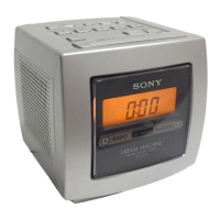
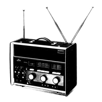
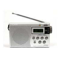
Device controls and their functions.

SECTION 2 DISASSEMBLY

2-1. Cabinet (Front) ASSY, "Cabi, rear" Disassembly

Disassembly procedure for front and rear cabinets.

2-2. MD ASSY Disassembly

Disassembly procedure for the MD ASSY.

2-3. Head, Motor, and Belt Disassembly

Disassembly of heads, motors, and belts.

2-4. Circuit Board Disassembly

Disassembly of Jack, Main, and Fine Tune boards.

2-5. Battery and Power Board Disassembly

Disassembly of Battery Terminal and Power boards.

2-6. Installation Notes

Guidelines for wiring and component installation.

2-7. Dial Pointer Setting

Procedure for setting the dial pointer.

SECTION 3 TEST MODE

3-1. Mechanical Adjustments

Procedures for mechanical adjustments (torque, tension).

3-2. Electrical Adjustments

Procedures for electrical adjustments (tape speed, azimuth).

SECTION 4 DIAGRAMS

4-1. Block Diagrams

System functional block diagrams.

4-2. Printed Wiring Boards

Printed circuit board layouts.

4-3. Schematic Diagram - Main Section (1/2)

Main section electrical schematic (part 1).

4-4. Schematic Diagram - Main Section (2/2)

Main section electrical schematic (part 2).

SECTION 5 EXPLODED VIEWS

5-1. Front Cabinet Section

Exploded view of the front cabinet assembly.

5-2. Rear Cabinet Section

Exploded view of the rear cabinet assembly.

5-3. Mechanism Deck Section-1

Exploded view of mechanism deck part 1.

5-4. Mechanism Deck Section-2

Exploded view of mechanism deck part 2.

SECTION 6 ELECTRICAL PARTS LIST

Board-Specific Parts Lists

Parts lists for specific boards.

Semiconductor and Passive Components

Lists of semiconductor and passive components.

Connectors and Jacks

Lists of connectors and jacks.
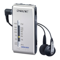
Related product manuals