3
CFM-S1
1
2
Screws
+ BVTP 3X10
Chassis(B)
MD ASSY
pointer
Cabi, rear
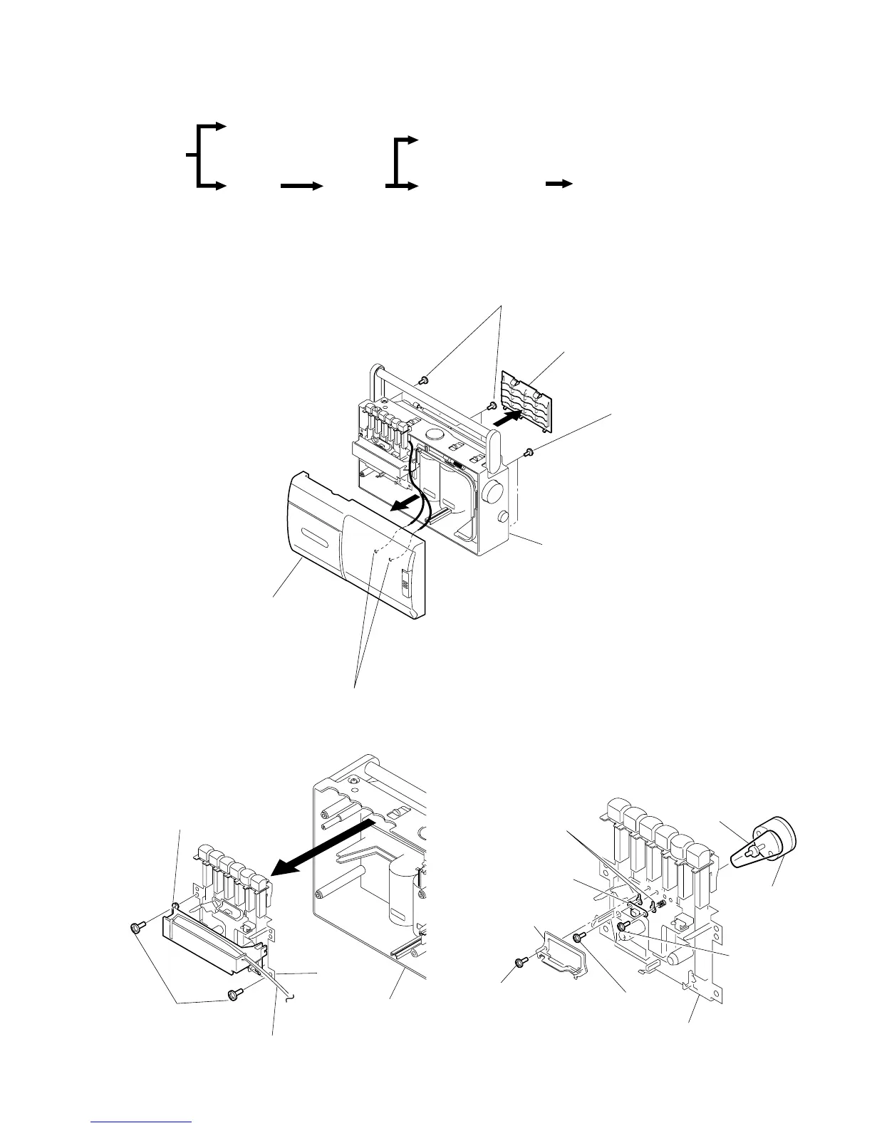
SECTION 2
DISASSEMBLY
Note : Follow the disassembly procedure in the numerical order given.
2-1. CABINET (FRONT) ASSY, “CABI, REAR”
2-2. MD ASSY
• The equipment can be removed using the following procedure.
Set
Cabinet (front) ASSY
Cabi, rear
Jack board, Main board,
Fine tune board
Battery terminal board, Power board
MD ASSY
Record/playback head (HRP101),
Reel/capstan motor (M101), Belt
3
1
4
Remove solder (two places)
2
Screws + BVTP 3X14
2
Screws + BVTP 3X1
Lid, BATT
Cabinet(front) ASSY
Cabi, rear
2-3. RECORD/PLAYBACK HEAD (HRP101),
REEL/CAPSTAN MOTOR (M101), BELT
1
Screws Tapping+B
MD ASSY
4
Record/playback
head (HRP101)
7
Reel/capstan
motor (M101