EasyManua.ls Logo

Sony CFM-20

Sony CFM-20
24 pages
To Next Page IconTo Next Page
To Previous Page IconTo Previous Page
Loading...
5
CFM-20
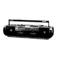
2-5. BATT (+) BOARD, POWER BOARD
(AEP, UK, IT, CET, HK, SP, AR model)
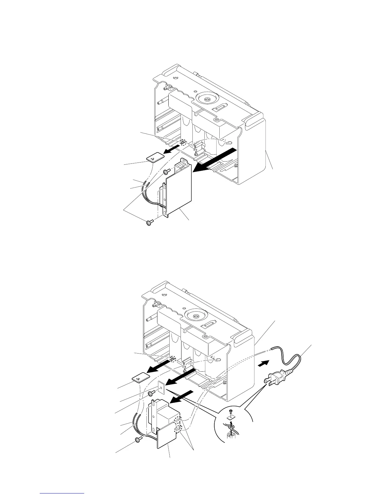
2-6. BATT (+) BOARD, POWER BOARD
(C&SA, MX, TW model)
Note on attaching power cord
On attaching power cord, first,
turn it around the projection on
"Cabi, rear" as shown in the
figure and secure it with "PWB,
cord retainer".
2
4
6
8
3
Screw
(+ BVTP 3X10)
1
Claw
Power board
Cord, powe
r
Batt (+) board
PWB, Cord retainer
White
Red
5
7
Screws
(+ BVTP 3X10)
Remove solder
(two places)
Cabinet (rear)
1
2
4
Claw
3
Screws
(+ BVTP 3X10)
Power board
Batt (+) board
Red
White
Cabinet (rear
)

Related product manuals