EasyManua.ls Logo

Sony CRF-230B - Page 25

Sony CRF-230B
60 pages
Print Icon
To Next Page IconTo Next Page
To Previous Page IconTo Previous Page
Loading...
CT408
CT407
CT405
Mw
SW1
ose
:
Mid
tiamer
MW
rf
trimmer
CT404
SW1
rf
‘lFT401
trimmer
iY
L404
SW1
rf
coil
L401
\
SW1
ant
coil
=
trimmer
L409
L402
LW
osc
coil
LW
ant
coil
LW
ant
eee
D,
L406
trimmer
&
LW
rf
coil
L403
:
hs
oS
L405
MW
ant
coil
trimmer
MW
ff
coil
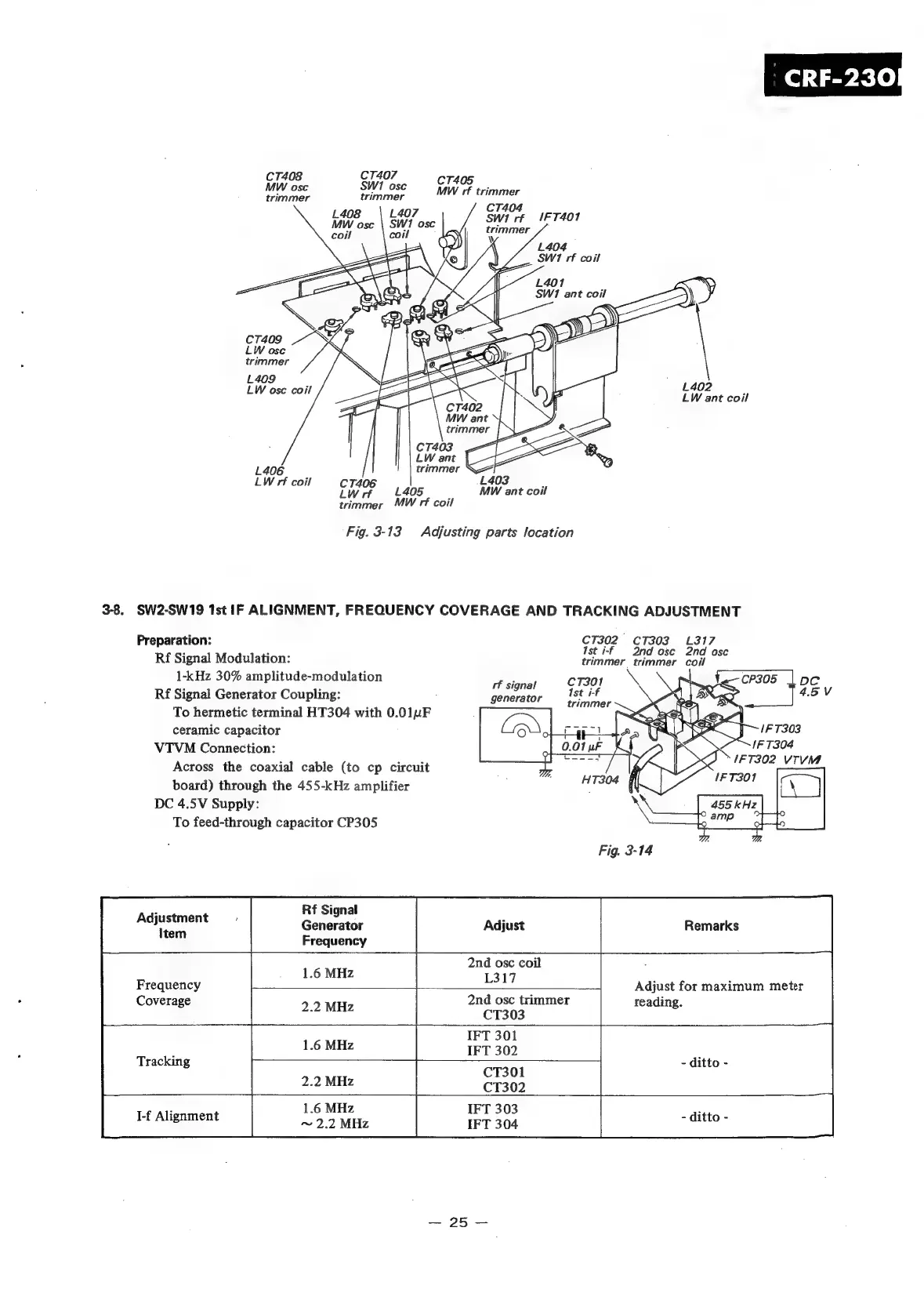
Fig.
3-13
Adjusting
parts
location
3-8.
SW2-SW19
1st
IF
ALIGNMENT,
FREQUENCY
COVERAGE
AND
TRACKING
ADJUSTMENT
Preparation:
yeu
cee
oy?
: .
I
na
osc
na
asc
Rf
Signal
Modulation:
trimmer trimmer
coil
:
1-kHz
30%
amplitude-modulation
1
tional
CT301
i.
cP305
loc
Rf
Signal
Generator
Coupling:
To
hermetic
terminal
HT304
with
0.01uF
ceramic
capacitor
VTVM
Connection:
Across
the
coaxial
cable
(to
cp
circuit
board)
through
the
455-kHz
amplifier
DC
4.5V
Supply:
To
feed-through
capacitor
CP305
generator
455
kHz
©
amp
Fig.
3-14
Rf
Signal
Generator
Adjust
Remarks
Frequency
Adjustment
Item
2nd
osc
coil
1.6
MHz
L317
Frequency
-
Adjust
for
maximum
meter
Coverage
2.2
MHz
“a
Bees
aoe
reading.
IFT
301
6
MMe
IFT
302
Tracking
CT301
-
ditto
-
1.6
MHz
IFT
303
~
2.2
MHz
IFT
304
I-f
Alignment