31
D-EJ775
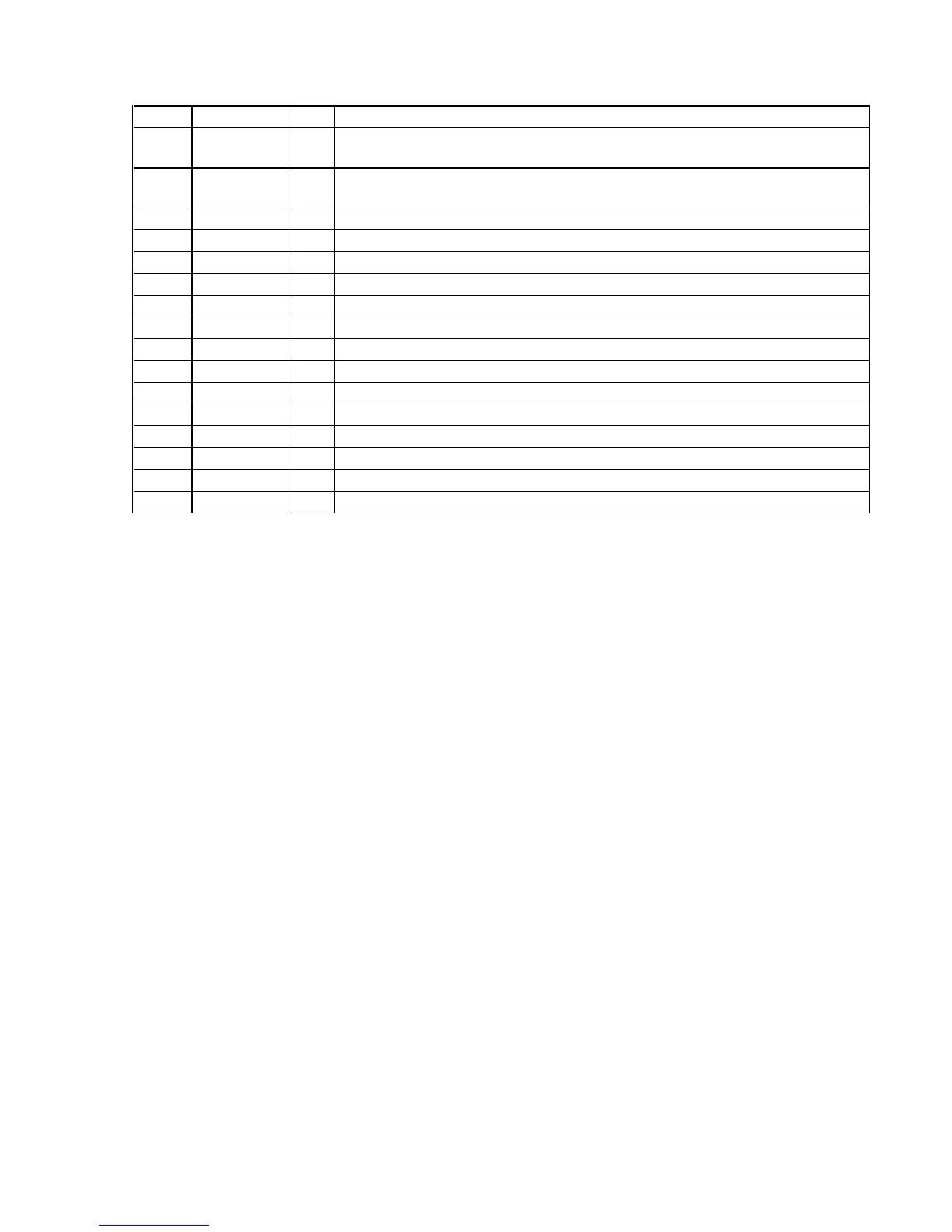
Pin No. Pin Name I/O Description
64, 65 C1, C0 —
Terminal for doubler circuit capacitor connection to develop liquid crystal display drive voltage
Not used
66 XWAKEUP O
Wakeup control signal output to the power control (for system standby reset)
“L”: wakeup The stop status is reset with the falling edge of input signal
67 PGM SDTO O Not used
68 PGMSI I Not used
69 PGM SCK O Not used
70 ESPLT O
ESP serial data latch pulse signal output to the DSP
71 GFS I Guard frame synchronous signal input from the DSP
72 FG I
FG pulse signal input from the spindle motor driver
73 PGMSEL O Not used
74 AMUTE O
Analog muting on/off control signal output to the headphone amplifier “H”: muting on
75 LEDDISP O
Charge LED drive signal output “L”: LED on
76 XRST O Reset signal output to the spindle motor driver and DSP “L”: reset
77 POFF O
Power off mode control signal output to the DSP “L”: power off mode
78 XOPSTBY O
Power on/off control signal output to the optical pick-up “H”: power on
79 OPG4 O
CD-RW gain control signal output to the optical pick-up “H”: gain up
80 C2POEN O
Not used