1-5
DCR-SR190E/SR200/SR200C/SR200E/SR290E/SR300/SR300C/SR300E_L2
ENGLISH JAPANESE
ENGLISH JAPANESE
1-3-3. E : 62 : 12 [Shift Lens Overheating (Yaw)] Occurred
Connect by the SeusEX and perform the following process.
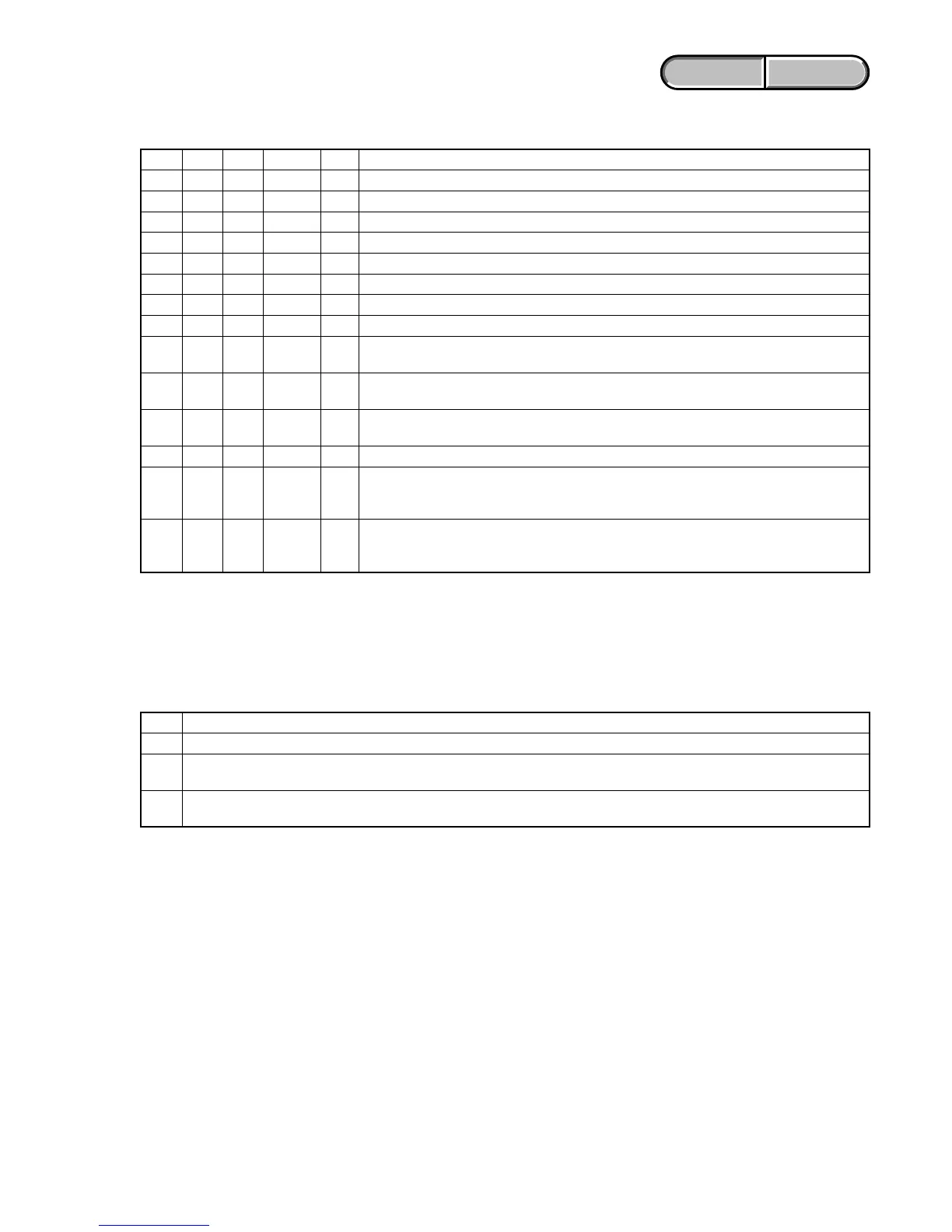
Order Block Page Address Data Procedure
111806BB2 01 Write the data.
211807D47 F0 Write the data.
311807D49 01 Write the data. (Note 1)
411807D49 00 Write the data.
511807D47 10 Write the data.
611807D49 01 Write the data. (Note 1)
711807D49 00 Write the data.
811806BB2 00 Write the data.
9
Check if the shift lens moves while setting the order 2 to 7. If the shift lens does not move,
replace the lens block (Note 2). When the shift lens moved, proceed to the order 10.
10
While setting the order 2 to 7, measure with an oscilloscope the output voltage of R5737 in the
periphery of IC5703 on the VC-492 board to check the output voltage varies.
11
If the output voltage does not vary, replace the lens block (Note 2). When the output voltage
varied, proceed to the order 12.
12 Turn the power OFF.
While measuring with an oscilloscope the output voltage of R5792 in the periphery of IC5703
13 on the VC-492 board, turn the power ON to check that the output voltage immediately after the
power on change as shown in Fig. 2.
If the output voltage change as shown in Fig. 2, replace the lens block (Note 2). If it does not
14 change as shown in Fig. 2, inspect the camera control circuit (IC1803 of VC-492 board) pe
riphery.
Note 1: Finish this operation within 10 seconds. If it is likely to take more than 10 seconds, set block: 11, page: 80, address:
7D49, data: 00, and then retry.
Note 2: When the lens block was replaced, execute the necessary adjustment items referring to Service Manual, ADJ.
After the adjustment, make sure with the STEADYSHOT turned ON that the steadyshot functions appropriately in the
handheld operation.
1-3-4. E : 62 : 20 [Abnormality of Thermistor] Occurred
Order Procedure
1Turn the power ON.
2
Check that R1846 in the periphery of IC1803 on the VC-492 board is 0 Ω and energizes. If it is not energizes, replace the R1846.
When R1846 is 0 Ω and energizes, replace the lens block (Note).
3
Check that no error occurs, after replacing the lens block and performing the necessary adjustment. If an error occurs, inspect
the camera control circuit (IC1803 of VC-492 board) periphery.
Note: When the lens block was replaced, execute the necessary adjustment items referring to Service Manual, ADJ.
After the adjustment, make sure with the STEADYSHOT turned ON that the steadyshot functions appropriately in the
handheld operation.