6-1
DCR-SR32E/SR33E/SR42/SR42A/SR42E/SR52E/SR62/SR62E/SR72E/SR82/SR82C/SR82E_ADJ
6. ADJUSTMENTS
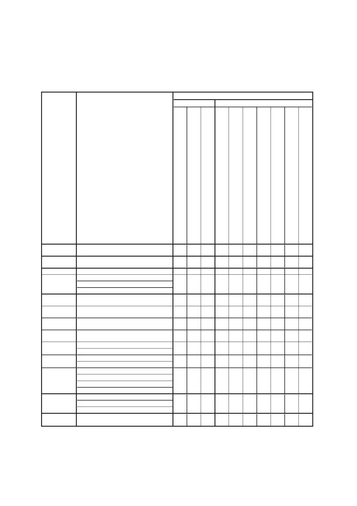
Table 6-1-1 (1)
Before starting adjustments
1-1. Adjusting items when replacing main parts and boards (Non MEGA model)
• Adjusting items when replacing main parts
When replacing main parts, adjust the items indicated by z in the following table.
Note 1: The Automatic Adjustment Program does not support.
Note 2: When replacing the HDD block, refer to “HDD Replacement Procedure”. (See page 6-11)
Lens device
HDD block (Note 2)
LCD block LCD901 (LCD panel)
CD-689 board IC7101 (CCD imager )
VC-489 board IC2101, X2101 (CPU, Oscillator)
VC-489 board IC1602 (S/H, AGC, A/D converter)
VC-489 board IC2901 (D/A converter)
DA-039 board IC3401 (Video, Audio I/O)
PD-317 board D6505 - 6507 (LCD backlight)
PD-317 board IC6501 (LCD driver)
Destination
Data Set
Destination data set
USB Serial No.
In
ut
USB serial No. input
(Note 1)
Origin oscillation check
z
S VIDEO OUT Y level adj.
S VIDEO OUT chroma level adj.
VIDEO OUT level check
CAMERA
ad
ustment 1
HALL adj.
z
CAMERA
ad
ustment 2
Flange back adj.
zz
CAMERA
ad
ustment 3
Flange back check
zz
CAMERA
ad
ustment 4
Optical axis adj.
zz
F No. standard data in
ut
MAX GAIN adj.
Color reproduction adj.
Color reproduction check
AWB standard data input
LV standard data input
AWB adj.
AWB check
LCD automatic adj. (VCO adj, Contrast adj.)
V-COM adj.
Transmissive moed white balance ad
.
z
z
z
z
z
zz
Touch panel
ad
ustment
z
Touch panel adj.
Parts replacementBlock replacement
z
Replaced parts
LCD
adjustment
Adjusting item
VIDEO
adjustment
Adjustment
z
CAMERA
adjustment 5
CAMERA
adjustment 6
CAMERA
adjustment 7
z
z
z
z
z
z
Ver. 1.7 2008.04