6-4
DCR-SR32E/SR33E/SR42/SR42A/SR42E/SR52E/SR62/SR62E/SR72E/SR82/SR82C/SR82E_ADJ
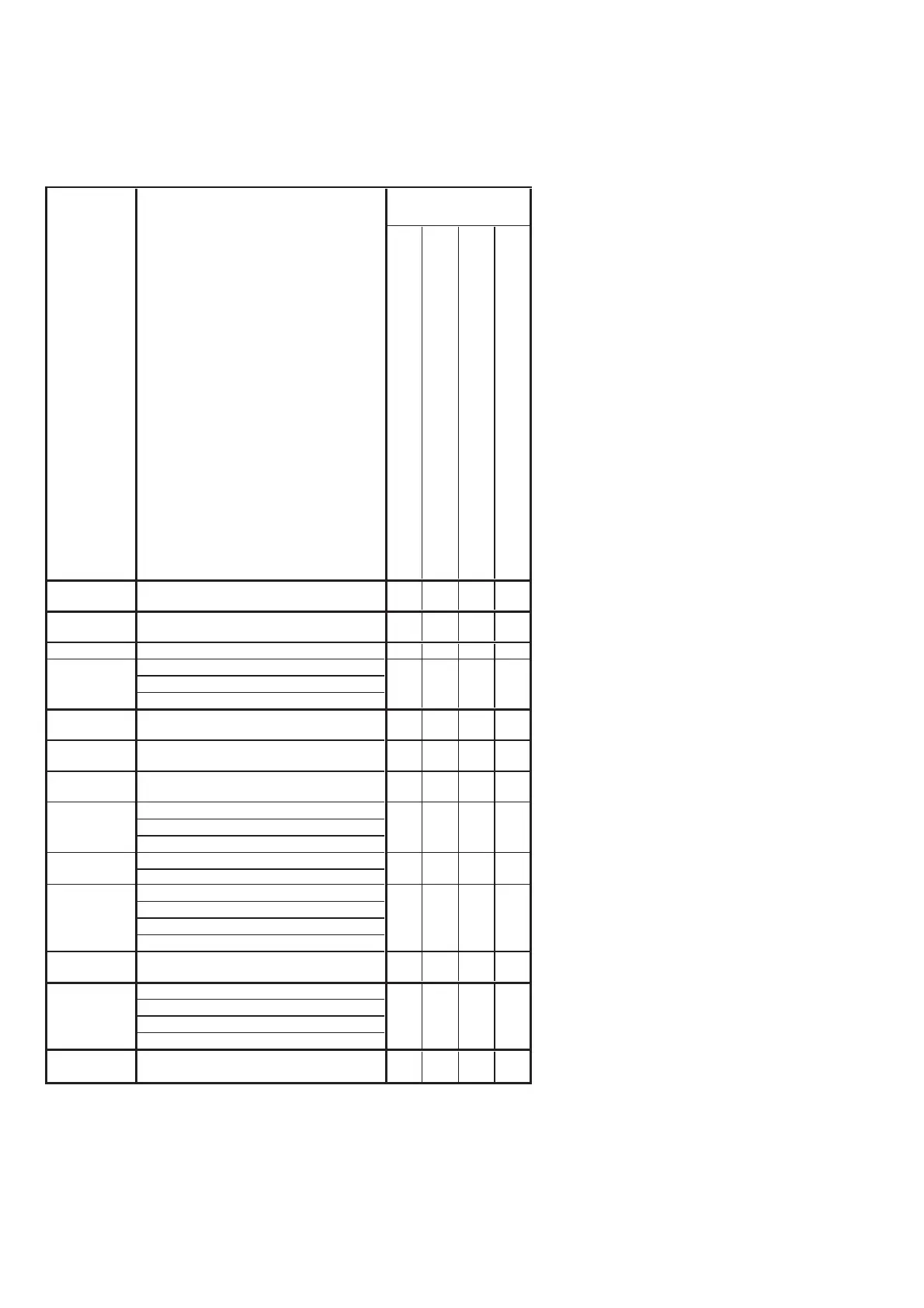
• Adjusting items when replacing a board
When replacing a board, adjust the items indicated by z in the following table.
Table 6-1-2 (2)
Note 3: IC2201 (Flash memory) on
the VC-489 board cannot be
replaced.
CD-672 board (COMPLETE)
DA-039 board (COMPLETE)
PD-318 board (COMPLETE)
VC-489 board (COMPLETE)
Destination
Data Set
Destination data set
z
USB Serial No.
In
ut
USB serial No. input
z
(Note 1)
Origin oscillation check
z
S VIDEO OUT Y level adj.
S VIDEO OUT chroma level adj.
VIDEO OUT level check
CAMERA
ad
ustment 1
HALL adj.
z
CAMERA
ad
ustment 2
Flange back and zoom lever center adj.
zz
CAMERA
ad
ustment 3
Flange back check
zz
F No. standard data in
ut
MAX GAIN adj.
Mechanical shutter adj
Color reproduction adj.
Color reproduction check
AWB standard data input
LV standard data input
AWB adj.
AWB check
CAMERA
ad
ustment 7
Steady shot check
zz
LCD automatic adj. (VCO adj, Contrast adj.)
V-COM adj.
Transmissive moed white balance ad
.
Reflective mode white balance ad
.
Board
replacement
z
zz
zz
z
LCD
adjustment
z
z
Touch panel
ad
ustment
Touch panel adj.
Adjusting item
Adjustment
VIDEO
adjustment
CAMERA
adjustment 4
CAMERA
ad
ustment 5
CAMERA
adjustment 6
z
zz
Ver. 1.7 2008.04