SERVICE MANUAL
DIGITAL VIDEO CASSETTE RECORDER
SPECIFICATIONS
RMT-814
US Model
DCR-TRV320/TRV520/TRV525/TRV720
Canadian Model
DCR-TRV320/TRV525/TRV720
AEP Model
DCR-TRV320E/TRV420E/TRV520E/TRV620E/TRV720E
UK Model
DCR-TRV320E/TRV620E
East European Model
North European Model
Russian Model
DCR-TRV320E
E Model
DCR-TRV320/TRV320E/TRV320P/
TRV520/TRV520E/TRV520P/TRV720/TRV720E
Hong Kong Model
DCR-TRV320/TRV320E/
TRV520/TRV520E/TRV720E
Korea Model
DCR-TRV320/TRV520/TRV720
Argentina Model
DCR-TRV520P
Australian Model
DCR-TRV320E/TRV520E
Chinese Model
DCR-TRV320E/TRV420E/TRV520E/TRV720E
Tourist Model
DCR-TRV520/TRV520E
B700 MECHANISM
– Continued on next page –
NTSC MODEL : DCR-TRV320/TRV320P/TRV520/TRV520P/TRV525/TRV720
PAL MODEL : DCR-TRV320E/TRV420E/TRV520E/TRV620E/TRV720E
For MECHANISM ADJUSTMENT, refer to
the “8mm Video MECHANICAL
ADJUSTMENT MANUAL
” (9-973-801-11).
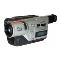
Photo: DCR-TRV320
DCR-TRV320/TRV320E/TRV320P/TRV420E/
TRV520/TRV520E/TRV520P/TRV525/
TRV620E/TRV720/TRV720E
Video camera
recorder
System
Video recording system
2 rotary heads
Helical scaning system
Audio recording system
Rotary heads, PCM system
Quantization: 12 bits (Fs 32 kHz,
stereo 1, stereo 2), 16 bits
(Fs 48 kHz, stereo)
Video signal
DCR-TRV320/TRV320P/TRV520/
TRV520P/TRV525/TRV720 :
NTSC color, EIA standards
DCR-TRV320E/TRV420E/TRV520E/
TRV620E/TRV720E :
PAL colour, CCIR standards
Recommended cassette
Hi8/Digital8 video cassette
Recording/Playback time (using
120 min. Hi8 video cassette)
SP mode: 1 hour
LP mode: 1 hour and 30 minutes
Fastforward/rewind time (using
120 min. Hi8 video cassette)
Approx. 5 min.
Viewfinder
Electric Viewfinder (monochrome)
Image device
1/4 type CCD (Change Coupled
Device)
DCR-TRV320/TRV320P/TRV520/
TRV520P/TRV525/TRV720 :
Approx. 460,000 pixels
(Effective: Approx. 290,000 pixels)
DCR-TRV320E/TRV420E/TRV520E/
TRV620E/TRV720E :
Approx. 800,000 pixels
(Effective: Approx. 400,000 pixels)
Lens
Combined power zoom lens
Filter diameter 37 mm (1 1/2 in.)
25× (Optical)
DCR-TRV320/TRV320E: E, AUS, HK,
CN/TRV320P/TRV420E: CN/TRV520/
TRV520E: E, AUS, HK, CN, JE/
TRV520P/TRV525/TRV720/TRV720E:
E, HK, CN :
450× (Digital)
DCR-TRV320E: AEP, UK, EE, NE, RU/
TRV520E: AEP/TRV620E/TRV720E:
AEP :
100× (Digital)
DCR-TRV420E: AEP :
125× (Digital)
Focal length
3.7 - 92.5 mm (5/32 - 3 3/4 in.)
When converted to a 35 mm still camera
48 - 1200 mm (1 15/16 - 47 1/4 in.)
Colour temperature
Auto
Minimum illumination
DCR-TRV320/TRV320P/TRV520/
TRV520P/TRV525/TRV720 :
1 lux (F 1.6)
DCR-TRV320E/TRV420E/TRV520E/
TRV620E/TRV720E :
3 lux (F 1.6)
0 lux (in the NightShot mode)*
* Objects unable to be seen due to the
dark can be shot with infrared
lighting.
Input/output
connectors
DCR-TRV320/TRV320P/TRV520/
TRV520P/TRV525/TRV720 :
S video input/output
4-pin mini DIN
Luminance signal: 1 Vp-p,
75 ohms, unbalanced
Chrominance signal: 0.286 Vp-p,
75 ohms, unbalanced
Audio/Video input/output
AV MINIJACK, 1 Vp-p, 75 ohms,
unbalanced, sync negative
327 mV, (at output impedance more than
47 kilohms)
Output impedance with less than 2.2
kilohms/Stereo minijack (ø 3.5 mm)
Input impedance more than 47 kilohms
DCR-TRV320E: E, AUS, HK, CN/
TRV420E: CN/TRV520E: E, AUS, HK,
CN, JE/TRV620E/TRV720E :
S video input/output
4-pin mini DIN
Luminance signal: 1 Vp-p,
75 ohms, unbalanced
Chrominance signal: 0.3 Vp-p,
75 ohms, unbalanced
Audio/Video output
AV MINIJACK, 1 Vp-p, 75 ohms,
unbalanced, sync negative
327 mV, (at output impedance more than
47 kilohms)
Output impedance with less than 2.2
kilohms/Stereo minijack (ø 3.5 mm)
DCR-TRV320E: AEP, UK, EE, NE, RU/
TRV420E: AEP/TRV520E: AEP :
TM
When the machine needs to be repaired,
please refer to page 9 to discriminate
the type of LCD.
Ver 1.4 2004. 09