EasyManua.ls Logo

Sony Digital8 DCR-TRV410 User Manual

Sony Digital8 DCR-TRV410
204 pages
To Next Page IconTo Next Page
Page #1 background imageLoading...
Page #1 background image
DCR-TRV410/TRV410E/
TRV510/TRV510E
RMT-814
US Model
Canadian Model
DCR-TRV510
AEP Model
UK Model
DCR-TRV410E/TRV510E
E Model
Hong Kong Model
Tourist Model
DCR-TRV410/TRV410E
Australian Model
Chinese Model
DCR-TRV410E
MICROFILM
B800 MECHANISM
DIGITAL VIDEO CAMERA RECORDER
Photo: DCR-TRV510
For MECHANISM ADJUSTMENT, refer to
the “8mm Video MECHANICAL
ADJUSTMENT MANUAL
(9-973-801-11).
SPECIFICATIONS
Abbreviation
HK : Hong Kong model
JE : Tourist model
AUS : Australian model
CN : Chinese model
NTSC MODEL : DCR-TRV410/TRV510
PAL MODEL : DCR-TRV410E/TRV510E
SERVICE MANUAL
Ver 1.0 1999.03

Table of Contents

Question and Answer IconNeed help?

Do you have a question about the Sony Digital8 DCR-TRV410 and is the answer not in the manual?

Sony Digital8 DCR-TRV410 Specifications

General IconGeneral
Video FormatDigital8
Optical Zoom20x
Image SensorCCD
ViewfinderColor
Image StabilizationElectronic
Image Sensor Size1/4 inch
MicrophoneStereo
USBNo
LCD Screen2.5-inch
Camcorder Media TypeDigital8
Recording MediaDigital8 Tape
Battery TypeInfoLithium
ConnectivityComposite video/audio output

Summary

SERVICE MANUAL

SPECIFICATIONS

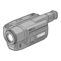
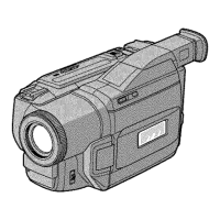
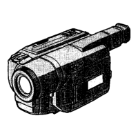
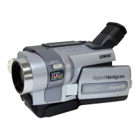
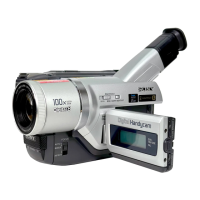
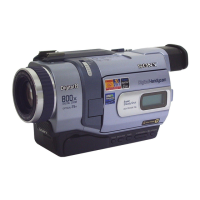
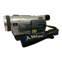
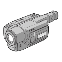
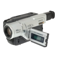
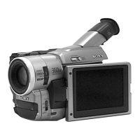
Technical specifications and features of the camcorder models.

Safety Precautions

Safety-Related Component Warning

Critical safety warnings for component replacement.

Safety Check-Out

Procedures to ensure safe operation after repair.

Service Notes

Power Supply During Repairs

Methods to prevent power shut-off during repair.

Force Eject Cassette Removal

Procedure for manually removing a cassette.

Self-Diagnosis Function

General Operations

Disassembly Procedures

Block Diagrams

Printed Wiring Boards and Schematic Diagrams

Adjustments

Camera Section Adjustments

Procedures for calibrating camera-related functions.

Mechanism Section Adjustments

Calibration steps for the camcorder's mechanical parts.

Video Section Adjustments

Calibration steps for the video signal processing circuits.

Servo and RF System Adjustments

Servo and RF System Adjustments Overview

Overview of servo and RF system calibration procedures.

Service Mode Operations

Repair Parts List

Self-Diagnosis Functions

Self-Diagnosis Code Table

Getting Started

Preparing the Power Supply

Steps for connecting the power adapter and installing the battery.

Recording a Picture

Viewing the Recording on TV

Photo Recording

Using the Program AE Function

Focusing Manually

Flash Memory Operations

Recording Still Images

Recording Still Images in Built-in Flash Memory

Changing Lithium Battery

Troubleshooting

Identifying Parts and Controls

Section 2 Disassembly

2-5. Mechanism Deck

2-10. Mechanism Deck, VC-213, DD-117, PJ-97 Boards

Section 3 Block Diagrams

3-3. Power Block Diagram (1)

3-4. Power Block Diagram (2)

Section 4 Printed Wiring Boards and Schematic Diagrams

4-2. Printed Wiring Boards and Schematic Diagrams

VC-213 Board (1/13) Camera Processor

VC-213 Board (2/13) Y/C Processor

VC-213 Board (3/13) Lens Motor Drive

VC-213 Board (4/13) I/O SEL, IR, BBI

VC-213 Board (5/13) VFD

VC-213 Board (6/13) SFD, TFD, LIP

VC-213 Board (7/13) TRX, TRF, TRW

VC-213 Board (8/13) 8mm PB RF AMP, D/A Converter

VC-213 Board (9/13) 8mm AFM Processor

VC-213 Board (10/13) 8mm Mechanism Control

VC-213 Board (11/13) DV Mechanism Control

VC-213 Board (13/13) HI Control

VC-213 Board (Side A)

PC-72 Board (2/3) Digi Still Cont, Flash Memory

PD-106 Board (1/2) RGB Decoder, LCD

PD-106 Board (2/2) Timing Gen., Back Light Drive

Section 5 Adjustments

Before Starting Adjustment

Preparation steps before starting adjustments.

1-1. List of Service Tools

Camera Section Adjustment

Adjustment procedures for the camera section.

5-1. Camera Section Adjustment

1-1. Preparations Before Adjustment (Camera Section)

Steps and tools needed before camera section adjustments.

1-1-2. Preparations

1-1-3. Precaution

1-2. Initialization of C, D, E, F Page Data

1-2-2. Initialization of D Page Data

1-2-3. Initialization of B Page Data

1-2-4. Initialization of E, F Page Data

1-3. Camera System Adjustments

1. Hall Adjustment

Adjusting hall AMP gain and offset for iris position.

2. Flange Back Adjustment (Using Minipattern Box)

3. Flange Back Adjustment (Using Chart and Subject)

3-1. Flange Back Adjustment(1)

Flange back adjustment using a chart at 2.0m.

3-2. Flange Back Adjustment (2)

Flange back adjustment using a chart >500m away.

4. Flange Back Check

5. Picture Frame Setting

Adjusting picture frame position using color bar chart.

6. AGC Gain Calibration Adjustment

7. Color Reproduction Adjustment

8. IRIS IN/OUT Adjustment

9. Auto White Balance Standard Data Input

10. Auto White Balance Adjustment

Calibrating the auto white balance output data.

11. White Balance Check

12. Angular Velocity Sensor Sensitivity Data Check

1-4. Color Electronic Viewfinder System Adjustments

1. EVF Initial Data Input

Inputting initial data for the EVF system.

2. VCO Adjustment (VF-126 board)

3. Bright Adjustment (VF-126 board)

Setting the LCD brightness level.

4. Contrast Adjustment (VF-126 board)

5. Backlight Consumption Current Adjustment (VF-126 board)

Adjusting backlight luminance and color temperature.

6. White Balance Adjustment (VF-126 board)

1-5. LCD System Adjustments

1. LCD Initial Data Input (1)

Inputting initial data for the LCD system.

2. LCD Initial Data Input (2)

Inputting secondary initial data for the LCD system.

5. VCO Adjustment (PD-106 board)

4. D Range Adjustment (PD-106 board)

Setting the D range for the LCD RGB decoder.

5. Bright Adjustment (PD-106 board)

6. Contrast Adjustment (PD-106 board)

Setting the LCD contrast level.

7. V-COM Level Adjustment (PD-106 board)

8. Color Adjustment (PD-106 board)

Adjusting color saturation for standard value.

9. V-COM Adjustment (PD-106 board)

10. White Balance Adjustment (PD-106 board)

Correcting white balance for the LCD screen.

5-2. Mechanism Section Adjustment

2-1. Hi8/Standard 8mm Mode

Procedures for Hi8/standard 8mm mode operation.

2-2-3. Overall Tape Path Check

Checking the overall tape path for signal integrity.

2-2-3. Overall Tape Path Check

5-3. Video Section Adjustment

3-1. Preparations Before Adjustments

Required instruments for video section adjustments.

3-1-2. Precautions on Adjusting

3-2. System Control System Adjustment

1. Initialization of B, C, D, E, F Page Data

Procedure to initialize page data.

2. Battery End Adjustment (VC-213 board)

Setting the battery end voltage for proper battery life.

3-3. Servo and RF System Adjustments

1. PLL f0 & LPF f0 Pre-adjustment (VC-213 board)

Pre-adjustment for PLL and LPF frequencies.

2. Switching Position Adjustment (VC-213 board)

Adjusting switching position for normal playback.

3. AGC Center Level Adjustment (VC-213 board)

4. APC & AEQ Adjustment (VC-213 board)

Adjusting APC and AEQ parameters.

5. PLL f0 & LPF f0 Final Adjustment (VC-213 board)

6. Hi8/standard 8mm Switching Position Adjustment (VC-213 board)

Adjusting switching position for Hi8/standard 8mm.

7. CAP FG Offset Adjustment (VC-213 board)

3-4. Video System Adjustments

1. 27MHz/36MHz Origin Oscillation Adjustment (VC-213 board)

Setting oscillation frequency for synchronization.

2. Chroma BPF f0 Adjustment (VC-213 board)

Setting chroma band-pass filter center frequency.

3. S VIDEO OUT Y Level Adjustment (VC-213 board)

4. S VIDEO OUT Chroma Level Adjustment (VC-213 board)

Adjusting S-Video chroma signal level.

5. VIDEO OUT Y, Chroma Level Check (VC-213 board)

6. Hi8/standard 8mm 14 MHz Origin Oscillation Adjustment (VC-213 board)

Setting oscillation frequency for Hi8/8mm playback.

7. BBI PLL Adjustment (VC-213 board)

9. Hi8/standard 8mm Chroma Level Adjustment (VC-213 board)

11. Hi8/standard 8mm RP Filter f0 Adjustment (VC-213 board)

3-4-2. BIST Check

1-4. IC301(SFD) BIST(PB) Check

2-3. IC301(SFD) BIST(REC) Check

3-5. IR Transmitter Adjustments

3. IR Audio Deviation Adjustment (VC-213 board)

3-6. Audio System Adjustments

2. Hi8/standard 8mm AFM 1.5 MHz Deviation Adjustment (VC-213 board)

5-4. Service Mode

4-3. Service Mode

2-2. F Page Emergence Memory Address

2-4. MSW Code

Section 6 Repair Parts List

6-2. Electrical Parts List

For Camera Color Reproduction Adjustment

Related product manuals