
A
April RiceAug 8, 2025
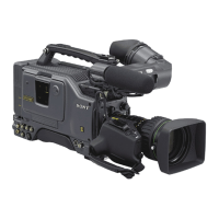
How to clean Sony DSR-570WSP when head clogs?
- MmichaeldavisAug 8, 2025
To address head clogs on your Sony Camcorder: 1. Load the DVL-12CL cleaning cassette, play it for about 5 seconds, and then eject it promptly. Remember to only use the DVL-12CL cleaning cassette tape to avoid abnormal wear or damage to the video head. 2. Do not reuse a rewound cleaning cassette tape. 3. Check if the head clog has been resolved. 4. If not, turn off the power. Using a cleaning cloth moistened with cleaning liquid, gently touch the cloth on the video head. Rotate the drum slowly in the head's rotating direction (leftward from the top) with your fingers to clean it. Avoid moving the cleaning cloth vertically over the video head to prevent damage.