6-49
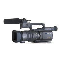
DSR-PD170/PD170P/PD190P
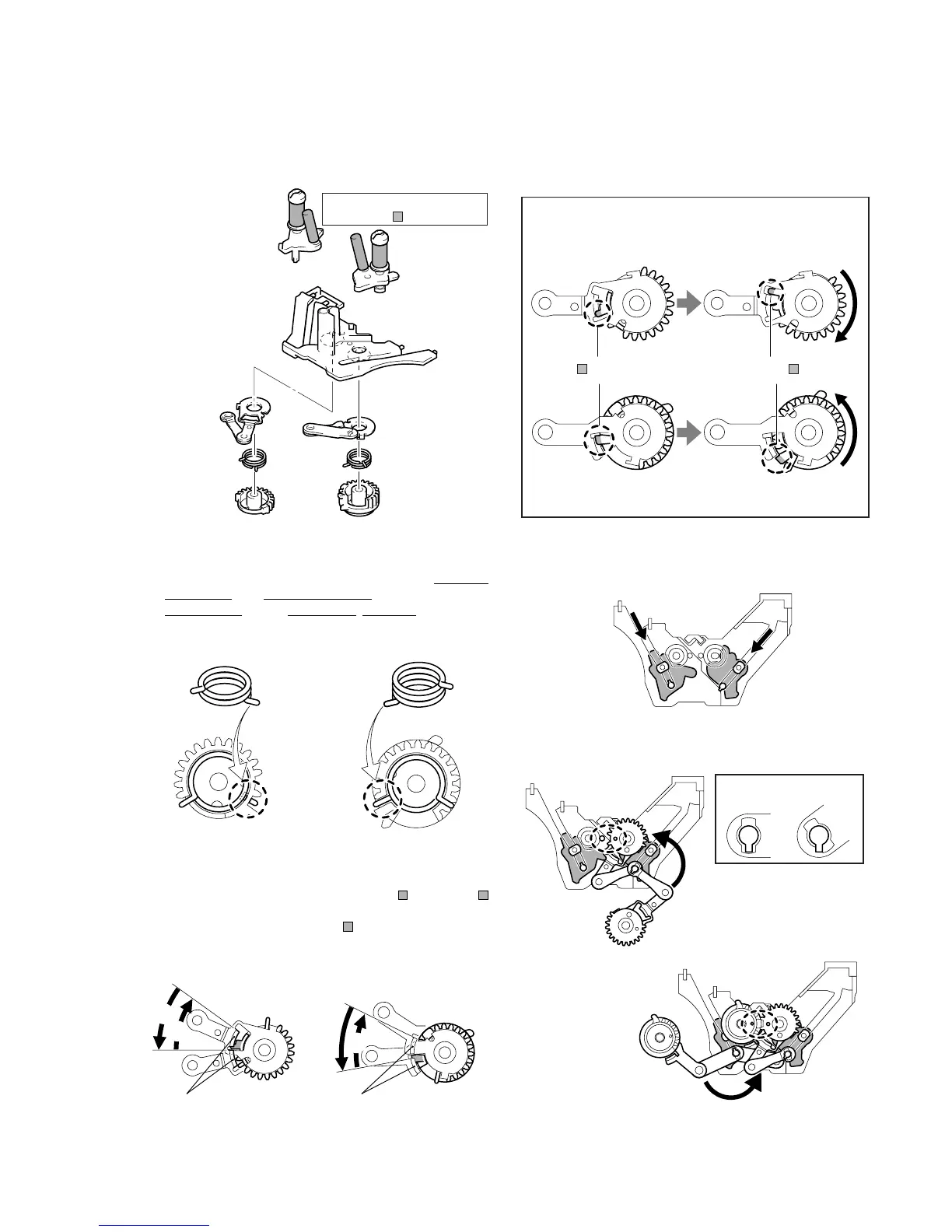
2-2-13. Coaster (S) / (T) Assembly, GL Arm (S) / (T) Assembly, Guide Rail, GL Gear (S) / (T) and
Torsion Spring (GLS) / (GLT)
Removing method
• Refer to the detailed diagram on the right, and remove each part.
Be careful not to touch the
tape guide ( part).
Be careful not to bend the GL arm.
Detailed diagram on removal of GL arm (S) / (T)
assembly
Guide rail
Coaster (T) assembly
GL arm (S) assembly
GL gear (S)
GL gear (T)
Torsion spring
(GLT)
GL arm (L) assembly
Torsion spring
(GLS)
Does not disconnect.
(S side)
Disconnects.
(S side)
The part is hooked.
Unhook the part.
Does not disconnect.
(T side)
Disconnects.
(T side)
Coaster (S) assembly
Assembling the GL Block Assembly
1. Attach the tension coil spring to each gear.
To differentiate the S side and T side, the side with more coils
is the T side. The S side has less coils. Face the ends of the
spring towards you, the tip of the coil (lower side) is positioned
at the right for the S side and at the left for the T side.
2. Hook the spring to the GL arm, and rotate in the ,2 direction
until the claw of the GL arm passes over the part, and the
becomes visible. When the GL arm is completely inserted, the
GL arm claw will pass below the part by the tension of the
spring (,3).
Torsion spring (GLS)
Torsion spring (GLT
Insert into hole.
Fit inside the notch.
1
1
2
2
3
3
Hook the spring.
Claw Claw
GL arm (S) assembly
GL arm (T) assembly
Hook the spring.
3. Attach the respective coaster assemblies.
4. Attach the GL gear block assembly in the order of the S and T
sides.
From the back of the guide rail.
Coaster (T) assembly
Coaster (S) assembl
 Loading...