SECTION 7
ELECTRICAL ADJUSTMENT
This section describes procedures and instructions necessary for adjusting electrical circuits in this set.
Instruments required:
1) Color monitor TV
2) Oscilloscope 1 or 2 phenomena, band width over 100 MHz, with delay mode
3) Frequency counter (over 8 digits)
4) Digital voltmeter
5) Standard commander (RMT-D195)
6) DVD reference disc
HLX-504 (J-6090-088-A) (single layer) (NTSC)
HLX-505 (J-6090-089-A) (dual layer) (NTSC)
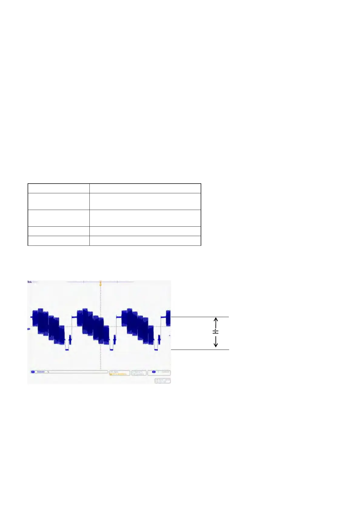
1. Checking Video Output Level
<Purpose>
This checks whether video output level satisfy the NTSC standard. If it is not correct, the brightness will be too large or small.
Mode Play
Signal
Check the color-bar (100%) signal on DVD
reference disc
Measurement Point
LINE OUT (VIDEO) connector
(75 Ω terminated)
Measuring Instrument Oscilloscope
Specification 1.00 ± 0.05 Vp-p
Checking method:
1) Confirm that the video output level is 1.00 ± 0.05 Vp-p.
7-1. STANDARDVIDEOLEVEL
DVP-FX97/FX980/FX980WM
7-1E