•
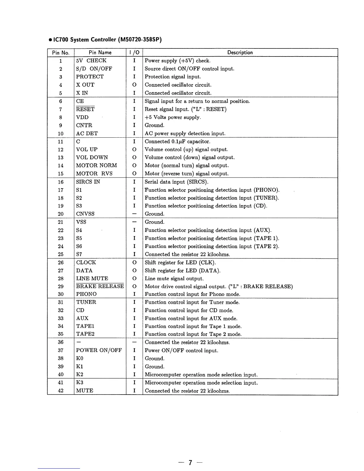
IC700 System
Controller
(M50720-358SP)
Pin
No.
Pin
Name
I/O
Description
1
5V
CHECK
I
Power
supply (+5V) check.
2
S/D
ON/OFF
I
Source direct
ON/OFF
control input.
3
PROTECT
I Protection
signal input.
4
X OUT
0
Connected oscillator circuit.
5
XIN
I Connected oscillator
circuit.
6
CE
I
Signal input for
a
return to normal position.
7
RESET
I
Reset signal input.
(”L”
: RESET)
8 VDD
I
-f
5
Volts
power
supply.
9
CNTR
I
Ground.
10
AC
DET
I
AC
power
supply detection
input.
11
C
I
Connected O.l^F capacitor.
12
VOL
UP o
Volume control (up)
signal
output.
13 VOL
DOWN
0 Volume control (down) signal
output.
14
MOTOR
NORM 0
Motor
(normal turn) signal output.
15
MOTOR RVS
0
Motor
(reverse turn) signal
output.
16
SIRCS
IN
I
Serial data input
(SIRCS).
17
SI
I
Function
selector
positioning
detection input (PHONO).
18
S2
I Function
selector
positioning
detection input
(TUNER).
19 S3
I Function selector
positioning
detection
input
(CD).
20
CNVSS
—
Ground.
21 VSS
—
Ground.
22 S4
I
Function selector
positioning detection
input
(AUX).
23
S5
I
Function
selector positioning detection input
(TAPE
1).
24 S6
I
Function selector
positioning detection input
(TAPE
2).
25
;
S7 I Connected the
resistor
22
kiloohms.
26
CLOCK
0 Shift register for
LED
(CLK).
27
DATA
o Shift
register for LED (DATA).
28 LINE MUTE
o
Line mute signal output.
29
BRAKE
RELEASE
o Motor drive
control
signal
output. (”L”
:
BRAKE RELEASE)
30
PHONO
I Function
control input
for
Phono
mode.
31
TUNER I
Function control
input
for Tuner
mode.
32 CD I Function
control input
for CD mode.
33
AUX I
Function
control
input for AUX
mode.
34 TAPE1 I
Function
control
input for Tape
1 mode.
35
TAPE2
I
Function control
input for Tape
2 mode.
36
— —
Connected
the resistor 22
kiloohms.
37
POWER ON/OFF
I
Power ON/OFF
control input.
38 K0
I Ground.
39
K1 I
Ground.
40 K2 I
Microcomputer
operation mode selection
input.
41
K3
I
Microcomputer
operation mode selection
input.
42
MUTE
I
Connected the
resistor 22 kiloohms.
-
7
-