EasyManua.ls Logo

Sony F519R User Manual

Sony F519R
23 pages
To Next Page IconTo Next Page
Page #1 background imageLoading...
Page #1 background image
SERVICE
MANUAL AEP
Mode!
Photo :
TA-F519R
SPECIFICATIONS
Amplifier
Continuous
RMS
power output (both
channels
driven
simultaneously)
Model for Germany
TA-F519R TA-F419R
DIN,
1
kHz
4 ohms
105W+
105
W
80
W +
80
W
8
ohms
85 W + 85 W 75 W
+
75
W
20 Hz -20
kHz
;
4
ohms
80
W + 80 W 75 W + 75 W
8 ohms
75 W +
75
W
65
W +
65
W
Model for
Scandinavian
countries, Switzerland, Spain
and Portugal
TA-F519R
TA-F419R
DIN, 1 kHz
6
ohms
100
W+
100
w 80 W
+
80
W
8
ohms
80
W +
80
W 70 W +
70
W
20 Hz-20
kHz
6
ohms
75 W
-f
75 W 70 W
+
70 W
8
ohms 70 W + 70
W
60
W
+
60
W
Mode! for other countries
TA-F519R
TA-F419R
DIN,
1 kHz
4 ohms 105
W+
105
W 80 W
+
80 W
8 ohms
85
W
+
85 W 75 W + 75 W
20 Hz -20
kHz
4
ohms
80W
+
80W
75
W +
75
W
8 ohms
75 W + 75 W
65
W + 65 W
Input
Input
jack
Jack type
Sensitivity
impedance
PHONO
(MM)
Phono
2.0
mV 50
kilohms
PHONO (MC) Phono
0.17
mV
100
ohms
TUNER,
CD,
AUX,
DAT/TAPE 1
TAPE 2
Phono
150
mV 50
kilohms
PHONO
(MM/MC):
only for
TA-F519R
S/N
TA-F519R
TA-F419R
PHONO
(MM)
76 dB
PHONO (MC)
94
dB
94 dB
TUNER, CD,
AUX,
DAT/TAPE
1
TAPE
2
103
dB
103 dB
Output
Output
jack
Jack type
Voltage/impedance
REC
OUT
Phono jack
Voltage 150
mV impedance
1
kohm
HEADPHONES
Stereo
phono
jack
Accepts
low and high
impedance
headphones
INTEGRATED
STEREO
AMPLIFIER
Question and Answer IconNeed help?

Do you have a question about the Sony F519R and is the answer not in the manual?

Sony F519R Specifications

General IconGeneral
ModelF519R
Power output70 watts per channel into 8Ω (stereo)
Dimensions430 x 150 x 375mm
TypeAmplifier
Signal-to-Noise Ratio103dB (line)

Summary

Specifications

Amplifier Power Output

Continuous RMS power output for both channels driven simultaneously.

Safety-Related Component Warning

Critical warning about safety-related components.

Identifying Parts and Controls

Front Panel Controls

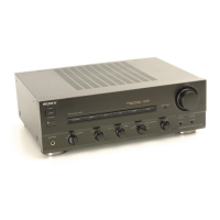
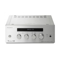
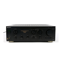
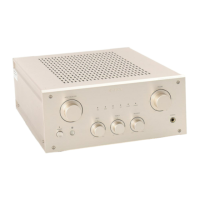
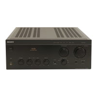
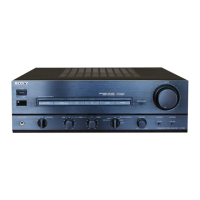
Identifies and describes functions of front panel controls.

Remote Commander Functions

Explains the functions of buttons on the remote commander.

Electrical Adjustments

DC Bias Adjustment Procedure

Step-by-step guide for DC bias adjustment.

Diagrams and Schematics

Circuit Board Locations

Identifies the locations of various circuit boards within the unit.

Schematic Diagrams

Presents detailed schematic diagrams of the unit's circuits.

Exploded Views

Front Panel Exploded View

Exploded view of the front panel assembly and parts.

Chassis Section 1 Exploded View

Exploded view of the chassis section 1 and its parts.

Chassis Section 2 Exploded View

Exploded view of the chassis section 2 and its parts.

Electrical Parts List

Related product manuals