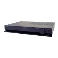
Do you have a question about the Sony HBD-TZ210 and is the answer not in the manual?
Highlights critical components for safe operation and replacement guidelines.
Addresses components containing confidential information and repair instructions.
Provides cautions for handling laser components and flexible boards.
Guidance on replacing chip components, especially tantalum capacitors.
Instructions and precautions for repairing flexible circuit boards.
Explains how to interpret self-diagnosis codes and take corrective actions.
Clears all data and resets the system to initial conditions.
Includes Display, Version, FL Pattern, and Key Test modes.
Moves optical pick-up and clears data for customer return after repair.
Identifies protection factors (SD, DC, TSD) when an error is detected.
Overview of IOP measurement for diagnosis and adjustment using remote.
Procedure to enter the DVD test mode via remote commander.
Standard procedures for executing IOP measurement on the DVD player.
Checks emergency history, including laser hours and error codes.
Displays firmware and software version details for various components.
Guidance on performing IOP measurement after replacing the optical pick-up.
Procedure for checking FM tuner sensitivity and reception.
Shows the signal flow and components in the RF section.
Illustrates the signal paths and components within the video processing section.
Depicts the signal flow and components in the audio processing section.
Shows the signal paths and components of the amplifier circuitry.
Illustrates the power supply circuitry and voltage distribution.
Schematic for the main board, covering RF and some system control components.
Schematic for the main board, detailing video processing and system control.
Schematic for the main board, focusing on SDRAM and interface components.
Schematic for the main board, showing motor drivers and control signals.
Schematic for the main board, detailing USB and audio interface components.
Schematic for the main board, showing bus buffers and power control ICs.
Schematic for the main board, detailing digital power amplifiers.
Schematic for the main board, showing power amplifier control and output stages.
Schematic for the SCART interface board.
 Loading...