36
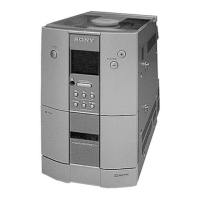
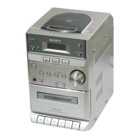
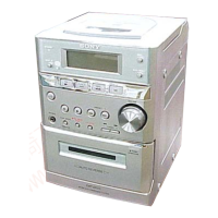
HCD-EC50
PANEL BOARD IC701 MB90802-108 (SYSTEM CONTROLLER)
Pin No. Pin Name I/O Description
1 P24 O Power relay control signal ourput
2 P25 O Amp control signal output
3 P26 O System reset signal output to the RF AMP
4 P27 O Control signal output to the PB/REC EQ AMP
5 P30/SO3 O Serial data output to the MP3 decoder
6 P31/SC3 O Serial data transfer clock signal output to the MP3 decoder
7P32/SI3 I Serial data input
8 P33/TMCK O Latch pulse signal output to the RF AMP
9 P34/IC0 I Remote sencer signal input
10 P35/IC1 O Serial data latch pulse output to the MP3 decoder
11 P36/OCU0 O M-MUTE signal output to the MP3 decoder
12 P37/OCU1 O Data transfer request signal output to the MP3 decoder
13 X0A/P90 O Resonator output terminal (32.768kHz)
14 X1A/P91 I Resonator input terminal (32.768kHz)
15 VCC — Power supply terminal (+3.3V)
16 VSS — Grounnd terminal
17 P40/LED0 O STANDBY LED control signal output
18 P41/LED1 I CD switch (SW3) input terminal
19 P42/LED2 I CD switch (SW1) input terminal
20 P43/LED3 I CD switch (SW2) input terminal
21 P44/LED4 O Loading motor control signal output
22 P45/LED5/TOT0 O Loading motor control signal output
23 P46/LED6/TOT1 O Elevator up/down motor control signal output
24 P47/LED7/TOT2 O Elevator up/down motor control signal output
25 P50/TIN0 I CD chuck switch (SW7) input terminal
26 P51/TIN1 I CD close switch (SW6) input terminal
27 P52/TIN2/PPG0 I CD stoc switch (SW5) input terminal
28 P53/PPG1 I CD open switch (SW8) input terminal
29 P54/SI0 I Internal status (SENSE) input from the CD DSP
30 P55/SC0 O Serial data transfer clock signal output to the CD DSP
31 P56/SO0 O Serial data output to the CD DSP
32 AVCC — Power supply terminal (+3.3V)
33 P57/SI1 I Data input from the the tuner
34 P76 O Oscillator control signal output to the CD DSP
35 AVSS — Grounnd terminal
36 P60/AN0 I Power detection signal input
37 P61/AN1 I Key AD input1
38 P62/AN2 I Key AD input2
39 P63/AN3 I Tuner tuned status signal input
40 P64/AN4 I Bias signal input from the bias oscillation circuit
41 P65/AN5/INT0 I Key AD input3
42 P66/AN6/INT1 I Power down detection signal input
43 P67/AN7/INT2 I Subcode data request signal input terminal
44 VSS — Grounnd terminal
45 P70/AN8/INT3 — Not used (open)
46 P71/AN9/SC1 O Back light LED control signal output
47 P72/AN10/SO1 I SUFIX signal input (Connected to +3.3V)