14
HCD-FR1/FR8/FR9
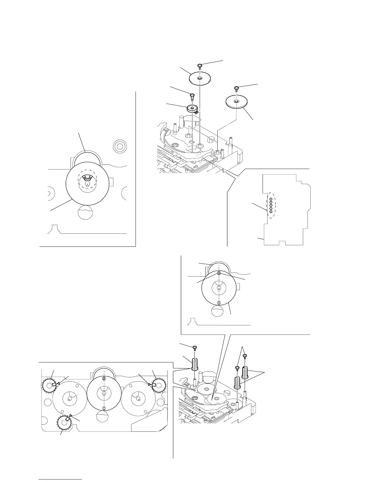
2-5. HOW TO INSTALL THE ROTARY ENCODER
(S702), GEAR (STOCKER COMMUNICATION)
2-6. HOW TO INSTALL THE CAM (STOCKER U/D)
2
five
solders
6
two gears
(stocker communication)
4
gear
(stocker communication)
RELAY board
7
two screws
(PTPWH2.6
×
8)
5
screw
(PTPWH2.6
×
8)
3
screw
(PWH2
×
6)
rotary encoder
(S702)
gear
(stocker
communication)
– rear –
1
rotary encoder
(S702)
Engage the rotary encoder (S702)
and the gear (stocker communication)
as shown below in the figure.
2
two cams
(stocker U/D)
2
cam (stocker U/D)
3
two screws
(PTPWH2.6
×
8)
3
screw
(PTPWH2.6
×
8)
rotary encoder
(S702)
hole
gear
(stocker communication)
– rear –
screw
1
Position the hole on the gear
(stocker communication) on the
screw of the rotary encoder (S702).
To install three cams (stocker U/D), align each groove
of the cam (stocker U/D) with each
f
mark on the
chassis as shown in the figure.
f
mark
f
mark
f
mark
cam (stocker U/D)
cam (stocker U/D)
cam (stocker U/D)
 Loading...


