16
HCD-FR1/FR8/FR9
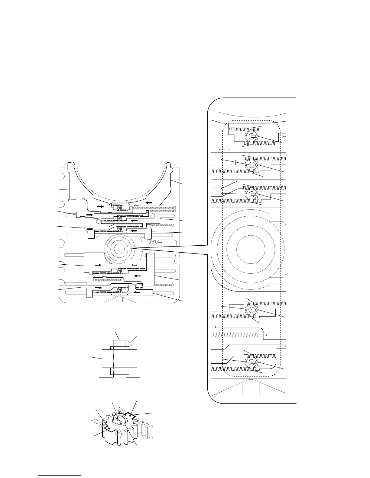
2-8. PHASE ADJUSTMENT BETWEEN PINIONS
(SLIDER) AND SLIDER-1 TO 5 (L/R)
A
A
A
A
A
A
1
As shown in the following figure, adjust the portion
A
of each slider to the boss with the
slider-1 to 5 (L) and the slider-1 to 5 (R) pushed in the arrow directions respectively (see Fig. 1).
2
Paying attention to the up/down direction of the pinion (slider) (see Fig. 2), install each pinion (slider)
so that the portion
B
of each pinion (slider) meshes with the portion
A
of each slider (see Fig. 3).
Note: Push in the pinion (slider) until the claw of the boss comes out above the pinion (slider) to lock.
pinion (slider)
pinion (slider)
pinion (slider)
pinion (slider)
pinion (slider)
pinion (slider)
pinion (slider) portion
B
slider portion
A
slider portion
A
boss
boss
boss
slider-5 (L)
slider-5 (R)
slider-4 (L)
slider-4 (R)
slider-3 (L)
slider-3 (R)
slider-2 (L)
slider-2 (R)
slider-1 (L)
slider-1 (R)
(Fig. 1)
(Fig. 2)
(Fig. 3)
A
A
A
A
boss
boss
boss
boss
claw
claw
pinion (slider) portion
B
 Loading...


