HCD-RV7/RV8
2121
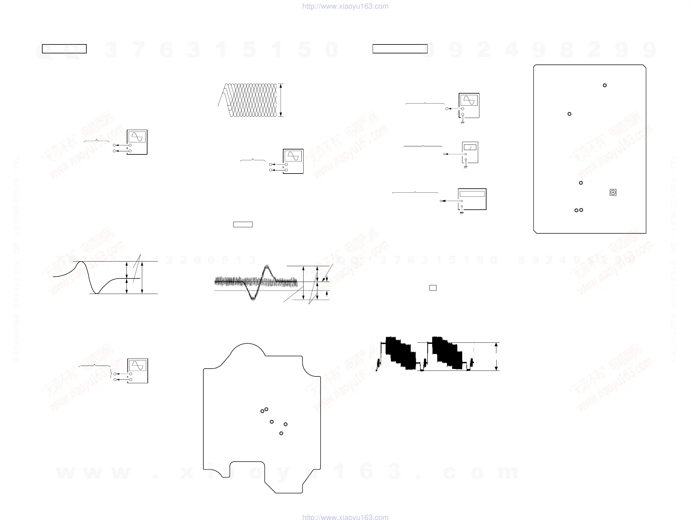
– VIDEO BOARD (Component Side) –
TP308
(V-OUT)
TP70
(54 MHz)
TP182
(4.2336 MHz)
TP415
(L-OUT)
TP413
(R-OUT)
RV501
Video
Level
Adjustment
– BD BOARD (Conductor Side) –
TP70
(TE)
TP68
(FE)
TP71
(RFDC)
TP73
(DVC)
TP72
(RFAC)
Note: Clear RF signal waveform means that the shape “ ◊ ” can be clearly
distinguished at the center of the waveform.
TRAVERSE LEVEL CHECK
Procedure :
1. Connect an oscilloscope to TP70 (TE) and TP73 (DVC) on the
BD board.
2. Turn the power ON.
3. Load a disc (LUV-P01) and playback the number nine track.
4. Press the hH button. (Becomes the 1 track jump mode.)
5. Confirm that the level B and A (DC voltage) on the oscilloscope
waveform.
Connecting Location:
Note:
1. CD Block is basically designed to operate without adjustment. Therefore,
check each item in order given.
2. Use LUV-P01 (Part No. 4-999-032-01) unless otherwise indicated.
3. Use an oscilloscope with more than 10MΩ impedance.
4. Clean the object lens by an applicator with neutral detergent when the
signal level is low than specified value with the following checks.
S-CURVE CHECK
Procedure :
1. Connect an oscilloscope to TP68 (FE) and TP73 (DVC) on the
BD board.
2. Turn the power ON.
3. Load a disc (LUV-P01) and actuate the focus search. (In
consequence of open and close the disc tray, actuate the focus
search)
4. Confirm that the oscilloscope waveform (S-curve) is
symmetrical between A and B. And confirm peak to peak level
within 2 ± 0.5 Vp-p.
Note: •Try to measure several times to make sure than the ratio
of A : B or B : A is more than 10 : 7.
•Take sweep time as long as possible and light up the
brightness to obtain best waveform.
RF LEVEL CHECK
Procedure :
1. Connect an oscilloscope CH1 to TP71 (RFDC), CH2 to TP72
(RFAC) and TP73 (DVC) on the BD board.
2. Turn the power ON.
3. Load a disc (LUV-P01) and playback the number nine track.
4. Confirm that oscilloscope waveform is clear and check if RF
signal level is correct or not.
level=1.2
±
0.55Vp-p
symmetry
A (DC voltage
center of
waveform
B
DVC
1 track jump waveform
TP70 (TE)
TP73 (DVC)
BD board
+
–
oscilloscope
RF signal waveform
VOLT/DIV : 200mV
TIME/DIV : 500ns
level : 0.75
±
0.1Vp-p (RFDC
1.05
±
0.3Vp-p (RFAC)
+
–
oscilloscope
TP71 (RFDC)
TP72 (RFAC)
BD board
TP73 (DVC)
symmetry
S-curve waveform
within 2
±
0.5Vp-
A
B
+
–
oscilloscope
BD board
TP68 (FE)
TP73 (DVC)
CD SECTION VIDEO SECTION
VIDEO LEVEL ADJUSTMENT
(AUDIO LEVEL/VIDEO CLOCK/AUDIO SERVO
CLOCK CHECK)
Procedure :
1. Connect an oscilloscope to TP308 (V-OUT) on the VIDEO
board.
2. Connect a level meter to TP415 (L-OUT) and TP413 (R-OUT)
on the VIDEO board.
3. Connect a frequency counter to TP70 (54 MHz) and TP182
(4.2336 MHz) on the VIDEO board.
3. Turn the power ON.
4. Set a test disc (HLV-402 (Part No. 8-909-870-00))
5. Press three buttons x , [ENTER], and [OPEN/CLOSE]
simultaneously.
6. The message “MPEG AV TEST” is displayed on the fluorescent
indicator tube. Color bar signal outputs and sine-wave (1 kHz
0dB) appears.
7. Adjust the RV501 on the VIDEO board for 0.714 ± 0.05 Vp-p.
Note: TP308 (V-OUT) on the VIDEO board must be teminated by 75 Ω.
8. Confirm that the value of level meter is 2.5 ± 2.0 dBs. (If audio
output disappear, press the [PLAY MODE] button twice)
9. Confirm that the value of frequency counter is 54 MHz ± 400
Hz.
10. Confirm that the value of frequency counter is 4,2336 MHz.
11. Change disc to a MP3 test disc (MP3 1kHz 0dB sine-wave is
recorded)
12. Confirm that the value of level meter is 2.4 ± 2.0 dBs.
+
–
level meter
VIDEO board
TP415 (L-OUT)
TP413 (R-OUT)
VIDEO board
TP70 (54 MHz)
TP182 (4.2336 MHz)
+
–
frequency counter
VIDEO board
TP308 (V-OUT)
+
–
oscilloscope
0.714
±
0.05 Vp-p
Connecting and Adjustment Location:
w
w
w
.
x
i
a
o
y
u
1
6
3
.
c
o
m
Q
Q
3
7
6
3
1
5
1
5
0
9
9
2
8
9
4
2
9
8
T
E
L
1
3
9
4
2
2
9
6
5
1
3
9
9
2
8
9
4
2
9
8
0
5
1
5
1
3
6
7
3
Q
Q
TEL 13942296513 QQ 376315150 892498299
TEL 13942296513 QQ 376315150 892498299
http://www.xiaoyu163.com
http://www.xiaoyu163.com
 Loading...