8
HCD-X1
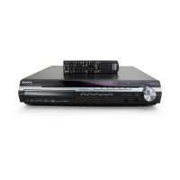
MAIN BOARD SERVICE POSITION
• In checking the MAIN board, prepare two extension jigs (Part No. J-2501-243-A: 1.00 mm Pitch, 17 cores, Length 300 mm and Part
No. J-2501-244-A: 1.00 mm Pitch, 21 cores, Length 300 mm).
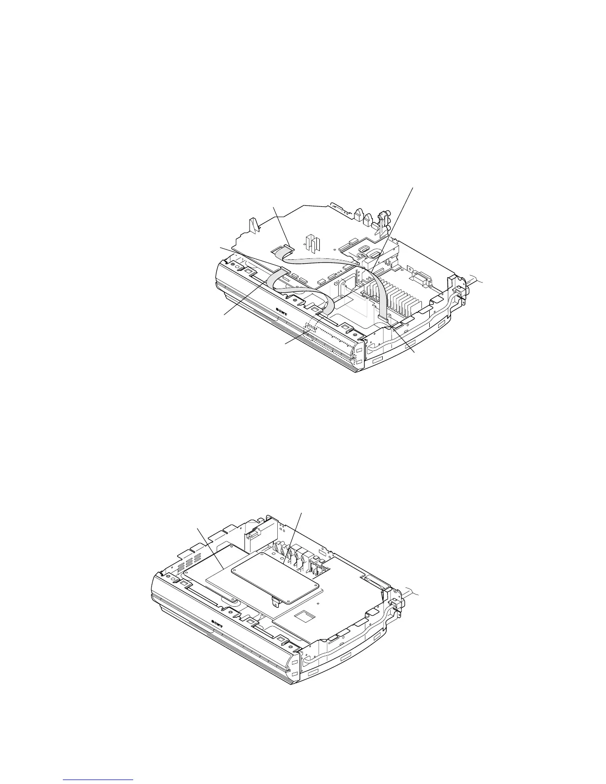
MIB01 BOARD (US, Canadian MODELS) SERVICE POSITION
MAIN board
(CN506)
POWER-AMP board
(CN301)
Connect extension jig (J-2501-244-A) to the
MAIN board (CN506) and POWER-AMP board (CN301).
Connect extension jig (J-2501-243-A) to the
MAIN board (CN505) and SWITCH board (CN801).
MAIN board
(CN505)
SWITCH board
(CN801)
Any to board
MIB01 board
 Loading...