9
HCD-X1
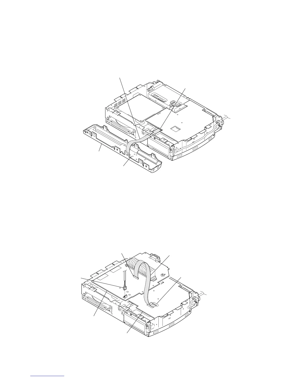
FRONT PANEL SECTION SERVICE POSITION
• In checking the front panel section, prepare extension jig (Part No. J-2501-243-A: 1.00 mm Pitch, 17 cores, Length 300 mm).
POWER-AMP BOARD SERVICE POSITION
• In checking the POWER-AMP board, prepare extension jig (Part No. J-2501-244-A: 1.00 mm Pitch, 21 cores, Length 300 mm).
MAIN board
(CN506)
POWER-AMP board
(CN301)
MAIN board
POWER-AMP board
Connect extension jig (J-2501-244-A) to the
MAIN board (CN506) and POWER-AMP board (CN301).
Note: Remove the MAIN Board once, and then remove the POWER-AMP board.
After that, reinstall the MAIN Board and set this service position.
Reconnect the
power cord.
MAIN board
(CN505)
SWITCH board
(CN801)
front panel section
Connect extension jig (J-2501-243-A) to the
MAIN board (CN505) and SWITCH board (CN801).
 Loading...