HMD-A400
– 5 –
TABLE OF CONTENTS
Section Title Page
1. GENERAL .................................................................. 1-1
2. DISASSEMBLY
2-1. Bucket Assembly Removal ................................. 2-1
2-2. A Board Removal ................................................ 2-1
2-3. D Board Removal ................................................ 2-2
2-4. Service Position .................................................... 2-3
2-5. H Board Removal ................................................. 2-4
2-6. Picture Tube Removal .......................................... 2-4
2-7. Harness Location .................................................. 2-5
3. SAFETY RELATED ADJUSTMENT............. 3-1
4. ADJUSTMENTS ...................................................... 4-1
5. DIAGRAMS
5-1. Block Diagrams ................................................... 5-1
5-2. Frame Schematic Diagram .................................. 5-5
5-3. Circuit Boards Location ...................................... 5-6
5-4. Schematic Diagrams and Printed Wiring Boards .. 5-7
(1) Schematic Diagram of H Board ......................... 5-8
(2) Schematic Diagram of A Board ......................... 5-9
(3) Schematic Diagrams of
D (a, b, c, d, e, f) Board .................... 5-15
5-5. Semiconductors .................................................. 5-27
6. EXPLODED VIEWS
6-1. Chassis ................................................................. 6-1
6-2. Picture Tube ........................................................ 6-2
6-3. Packing Materials ................................................ 6-3
7. ELECTRICAL PARTS LIST ............................ 7-1



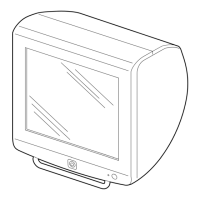


 To Next Page