Do you have a question about the Sony HT-CT770 and is the answer not in the manual?
Information on using lead-free solder for board assembly and its characteristics.
Procedure for safely discharging capacitors before board inspection to prevent electric shock.
Guidance on replacing specific ICs on the HDMI board, often requiring board replacement.
Guidance on replacing specific ICs on the main board, often requiring board replacement.
Troubleshooting symptom for the 'PROTECT' message on the display, with potential causes.
Guidance on replacing IC3001 and the main board, including thermal compound application.
Step-by-step outline of the set's disassembly procedure for service.
Procedure for disassembling the first part of the top panel assembly.
Procedure for removing the left and right channel woofer speaker units.
Steps for accessing and disassembling the first part of the main circuit board assembly.
Detailed steps for removing and handling the main circuit board during disassembly.
Procedure for disassembling and removing the power supply board unit.
Steps for disassembling and removing the HDMI interface board.
Procedure for disassembling and removing the Bluetooth wireless communication module.
Procedure to initialize system backup information and restore default settings.
Confirms display lighting, LED operation, button functions, and model/version information.
Enables display of the product's model name on the fluorescent indicator tube.
Confirms test tone output from each speaker for audio diagnostics.
Displays the subwoofer's µ-com version and tests wireless sound functionality.
Troubleshooting steps when 'PRTECT' is displayed, indicating a potential protection mode activation.
Steps to diagnose and resolve issues where HDMI video input is not shown.
Troubleshooting guide for diagnosing and fixing the problem of no audio output from the system.
Diagnostic steps for when the unit fails to power on, covering potential causes.
High-level overview of the HDMI signal path and related components.
Block diagram illustrating the main processing and signal flow within the unit.
Block diagram detailing the audio amplification stage and its connections.
Block diagram showing the panel interface and power supply circuitry.
Exploded view of the entire unit, showing major assembly sections and components.
Exploded view detailing the disassembly and components of the top panel assembly.
Exploded view illustrating the main board and its related components for access.
Exploded view showing the disassembly of the bottom cabinet and associated parts.
List of capacitors used in the unit, including part numbers, values, and tolerances.
List of coils used in the unit, including part numbers and inductance values.
List of semiconductor components like diodes and transistors with part details.
List of resistors used, including part numbers, resistance values, and power ratings.
List of integrated circuits used in the unit, with part numbers and function.
List of connectors, including part numbers and pin configurations.
List of diodes used in the unit, including part numbers and specifications.
| Brand | Sony |
|---|---|
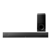
| Model | HT-CT770 |
| Category | Speaker System |
| Language | English |