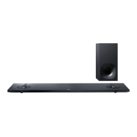
HT-NT5
3
1. SERVICING NOTES ............................................. 4
2. DISASSEMBLY
2-1. Disassembly Flow ........................................................... 9
2-2. Top Cabinet Block .......................................................... 10
2-3. TOUCH Board ................................................................ 11
2-4. DISPLAY Board Block ................................................... 11
2-5. SIRCS Board ................................................................... 12
2-6. DISPLAY Board ............................................................. 12
2-7. Organic EL Indicator Element (OLED1) ........................ 13
2-8. Connection Cable with Speaker (Woofer) ...................... 14
2-9. Connection Cable with Speaker (Tweeter) ..................... 15
2-10. Loudspeaker (Woofer) (SP1, SP2),
Loudspeaker (Tweeter) (SP3, SP4, SP5, SP6) ................ 16
2-11. RF Modulator Block ....................................................... 17
2-12. RF Modulator (RF1) ....................................................... 17
2-13. NFC Board ...................................................................... 18
2-14. BTW (WIFI) Board ......................................................... 19
2-15. WLAN/BT Combo Card (WIFI1)-1 ............................... 20
2-16. WLAN/BT Combo Card (WIFI1)-2 ............................... 21
2-17. Insulator (Top) ................................................................ 21
2-18. Power Cord (AC1) .......................................................... 22
2-19. POWER Board ................................................................ 22
2-20. AMP Board ..................................................................... 23
2-21. USB-CHUKEI Board ..................................................... 23
2-22. BTW (BT) Board ............................................................ 24
2-23. REPEATER Board .......................................................... 25
2-24. MB-1509 Board-1 ........................................................... 25
2-25. MB-1509 Board-2 ........................................................... 26
2-26. Bottom Chassis Block ..................................................... 27
2-27. MB-1509 Board Service Position ................................... 28
2-28. POWER Board Service Position ..................................... 28
3. TEST MODE ............................................................ 29
4. TROUBLESHOOTING .......................................... 38
5. DIAGRAMS
5-1. Block Diagram - HDMI Section - ................................... 41
5-2. Block Diagram - MAIN Section - ................................... 42
5-3. Block Diagram - AMP Section - ..................................... 43
TABLE OF CONTENTS
5-4. Block Diagram
- PANEL/POWER SUPPLY Section - ............................ 44
5-5. Printed Wiring Board - MB-1509 Board - ...................... 46
5-6. Printed Wiring Board - USB-CHUKEI Board - ............. 47
5-7. Schematic Diagram - USB-CHUKEI Board - ................ 47
5-8. Printed Wiring Board
- AMP Board (Side A) (Suffi x-11) - ............................... 48
5-9. Printed Wiring Board
- AMP Board (Side B) (Suffi x-11) - ............................... 49
5-10. Printed Wiring Board
- AMP Board (Side A) (Suffi x-12) - ............................... 50
5-11. Printed Wiring Board
- AMP Board (Side B) (Suffi x-12) - ............................... 51
5-12. Schematic Diagram - AMP Board (1/2) - ....................... 52
5-13. Schematic Diagram - AMP Board (2/2) - ....................... 53
5-14. Printed Wiring Boards - ANTENNA Section - ............... 54
5-15. Schematic Diagram - ANTTENA Section - .................... 54
5-16. Printed Wiring Board - TOUCH Board - ........................ 55
5-17. Schematic Diagram - TOUCH Board - ........................... 55
5-18. Printed Wiring Boards - DISPLAY/IR Section - ............ 56
5-19. Schematic Diagram - DISPLAY/IR Section -................. 57
5-20. Printed Wiring Board - POWER Board - ........................ 58
5-21. Schematic Diagram - POWER Board - .......................... 59
6. EXPLODED VIEWS
6-1. Overall Section ............................................................... 64
6-2. Top Cabinet Section ........................................................ 65
6-3. Bottom Cabinet Section .................................................. 66
6-4. Chassis Section ............................................................... 67
6-5. MAIN Board Section ...................................................... 68
7. ELECTRICAL PARTS LIST .............................. 69
Accessories are given in the last of the electrical parts list.
Note: The AMP board has been changed in the midway of production.
Refer to “Suffi x-11/Suffi x-12 discrimination of AMP board” on
page 45 about the distinguish of AMP board.

 Loading...