HT-ST7
4
SECTION 1
SERVICING NOTES
UNLEADED SOLDER
Boards requiring use of unleaded solder are printed with the lead-
free mark (LF) indicating the solder contains no lead.
(Caution: Some printed circuit boards may not come printed with
the lead free mark due to their particular size)
: LEAD FREE MARK
Unleaded solder has the following characteristics.
• Unleaded solder melts at a temperature about 40 °C higher
than ordinary solder.
Ordinary soldering irons can be used but the iron tip has to be
applied to the solder joint for a slightly longer time.
Soldering irons using a temperature regulator should be set to
about 350 °C.
Caution: The printed pattern (copper foil) may peel away if
the heated tip is applied for too long, so be careful!
• Strong viscosity
Unleaded solder is more viscous (sticky, less prone to fl ow)
than ordinary solder so use caution not to let solder bridges
occur such as on IC pins, etc.
• Usable with ordinary solder
It is best to use only unleaded solder but unleaded solder may
also be added to ordinary solder.
ADVANCE PREPARATION WHEN CONFIRMING OP-
ERATION
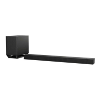
All of the units included in the HT-ST7 (SA-ST7/SA-WST7/EZW-
RT50) are required to confi rming operation of SA-ST7. Check in
advance that you have all of the units.
NOTE OF PERFORMING THE OPERATION CHECK IN
THE STATE THAT HEAT SINK WAS REMOVED
When performing the operation check in the state that this unit was
disassembled, it is possible to perform the operation check in the
state that heat sink was removed. But don’t perform the operation
check in the long time, and perform the operation check in the
volume state as low as possible.
NOTE OF REPLACING THE IC3506 ON THE MAIN
BOARD
IC3506 on the MAIN board cannot exchange with single. When
this part is damaged, exchange the complete mounted board.
NOTE OF REPLACING THE IC3001, IC3003, IC3005
AND IC3007 ON THE AMP BOARD AND THE COM-
PLETE AMP BOARD
When IC3001, IC3003, IC3005 and IC3007 on the AMP board and
the complete AMP board are replaced, it is necessary to spread the
compound between the AMP board and the heat sink.
Spread the compound referring to the fi gure below.
– AMP Board (Component Side) –
thermal compound
IC3001
IC3003 IC3005 IC3007
CAPACITOR ELECTRICAL DISCHARGE PROCESSING
When checking the board, for the electric shock prevention, con-
nect the resistors to both ends of respective capacitor (C519) to
discharge the capacitor (C519).
C519
– POWER Board (Conductor Side) –
800 :/2 W
ABOUT THE PAIRING METHOD
When the following repair is performed, the pairing of the Bar
speaker (SA-ST7) and Subwoofer (SA-WST7) is cut.
• Replacing of complete MAIN board
• Replacing of IC1002 on the MAIN board
Return the Bar speaker (SA-ST7) and Subwoofer (SA-WST7) to
the customer after performing the pairing according to the follow-
ing procedure.
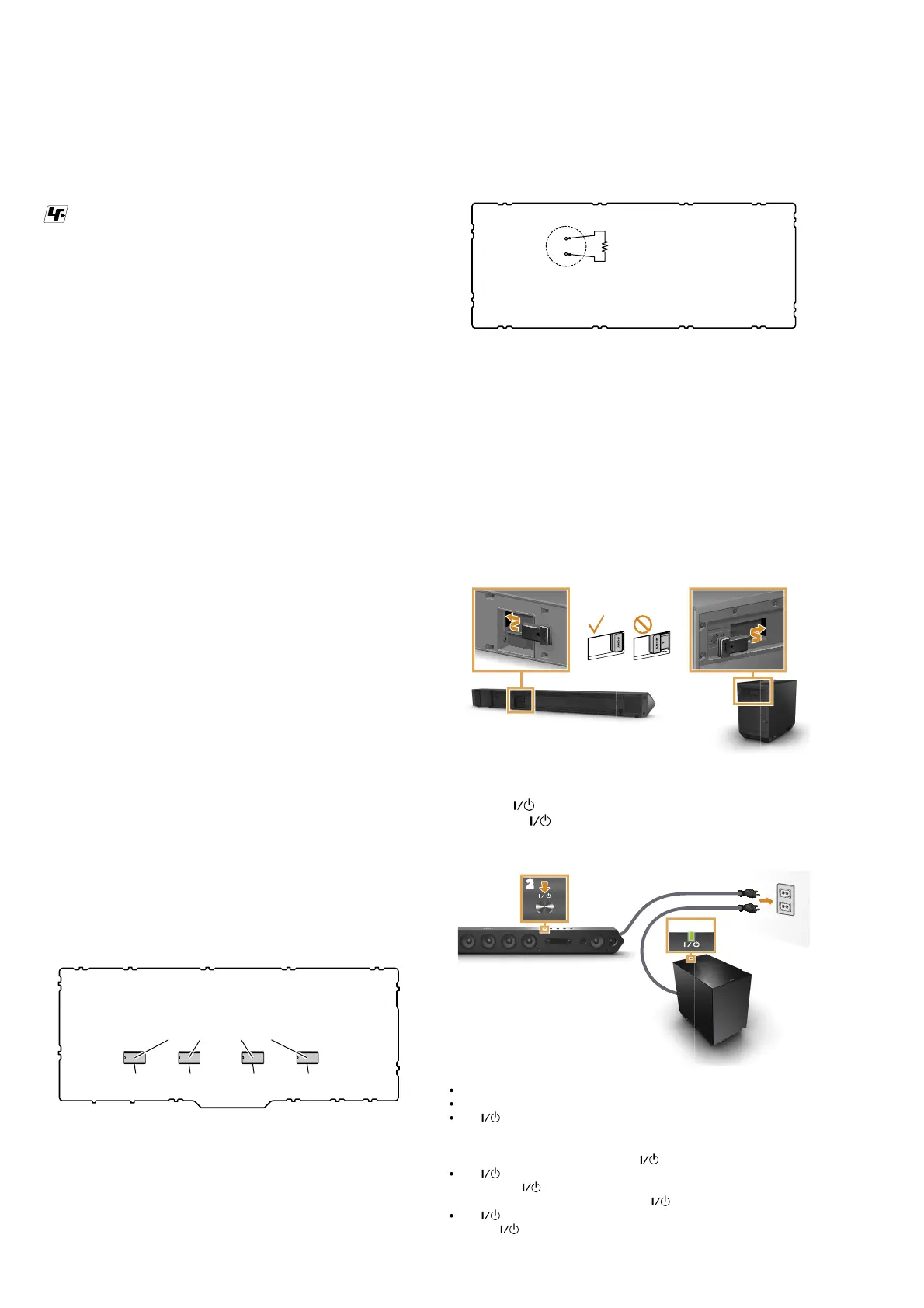
Preparation:
Insert the wireless transceivers (EZW-RT50) into the Bar speaker
(SA-ST7) and Subwoofer (SA-WST7).
Procedure:
1 Connect the AC power cords (mains leads).
2 Press the button on the Bar Speaker.
3 Confirm the indicator of the subwoofer is lit
in green. If not, the wireless transmission is not
activated.
No sound is output from the subwoofer.
indicator is off:
– Check that the AC power cord (mains lead) of the subwoofer is connected
securely.
– Turn the subwoofer on by pressing the
button on the subwoofer.
indicator flashes in green quickly:
First press the
button on the subwoofer, then insert the wieless transceiver
into the subwoofer correctly, and press the
button on the subwoofer again.
indicator flashes in red: If the
If the
If the
Make sure the AC power cord (mains lead) of the subwoofer is connected.
Make sure the wireless transceivers are inserted correctly.
Press the
button to turn off the subwoofer, and check that nothing is
blocking the ventilation holes of the subwoofer.

 Loading...