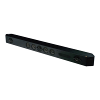
HT-ST7
7
Note: Follow the disassembly procedure in the numerical order given.
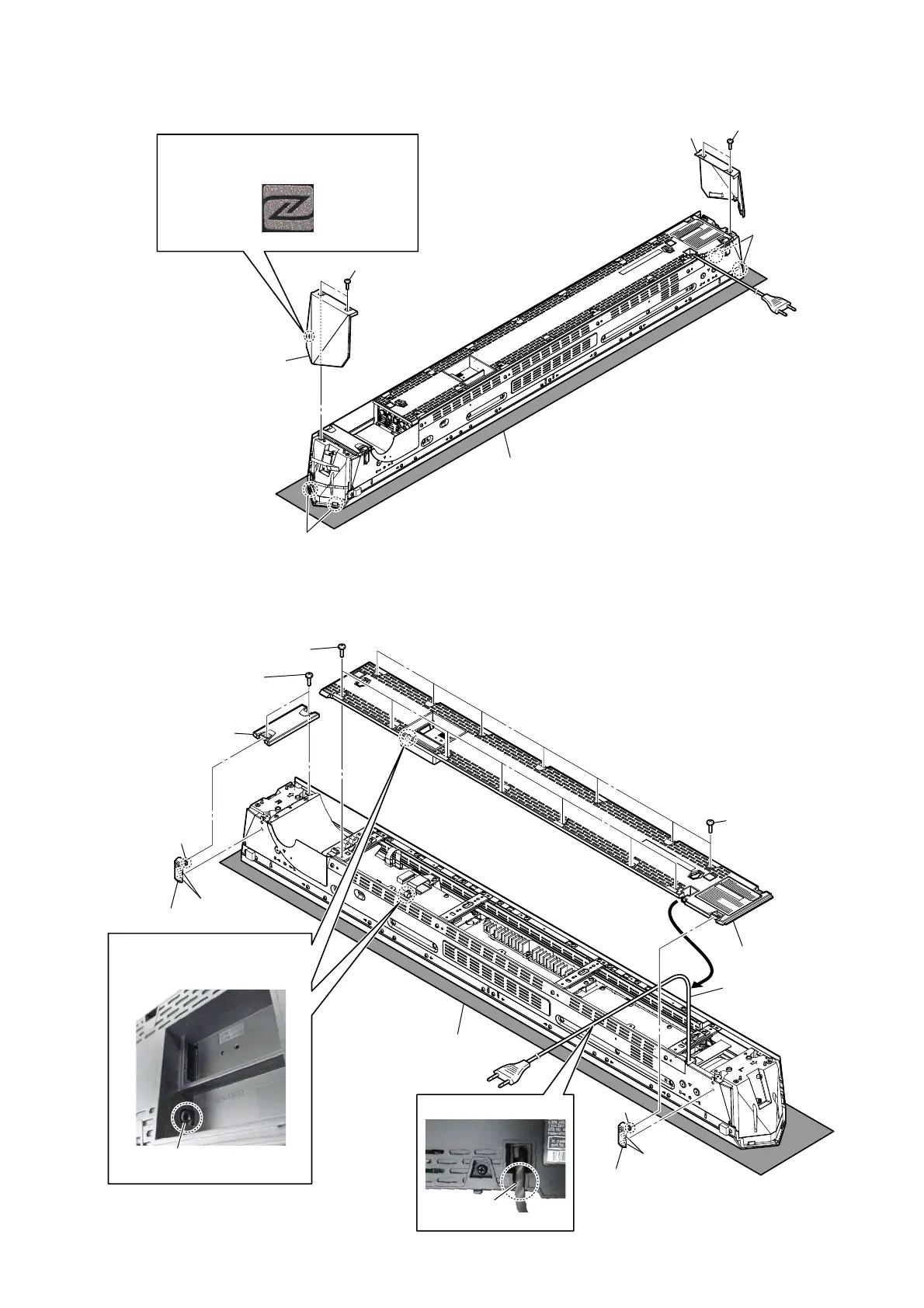
2-2. PANEL (L/R) ASSY
2-3. PANEL (REAR L) BLOCK, PANEL (REAR R)
1 two screws
(BVTP3 u 10)
1 two screws
(BVTP3 u 10)
Mark on the panel (R) assy
3 panel (L) assy
2 two claws
2 two claws
– Rear bottom view –
Note 1:
Please spread a sheet under
a unit not to injure front side.
Note 2:
When installing the panel (L/R) assy,
check the presence or absence of a mark,
do not mistake the right and left.
3 panel (R) assy
1 two bosses
2 claw
5 seven screws
(step) (BVTP3)
5 seven screws
(step) (BVTP3)
7 two screws
(step) (BVTP3)
3 foot (corner)
4 Remove the power cord
from the hook of panel
(rear L).
6 panel (rear L) block
8 panel (rear R)
3 foot (corner)
– Rear bottom view –
Note 1:
Please spread a sheet under
a unit not to injure front side.
1 two bosses
2 claw
Note 2:
When installing the panel,
check that J251 installed the
position shown in the figure.
J251
– Rear view –
power cord
– Rear view –
3ower ForG VettiQJ

 Loading...