Help Guide
Interchangeable Lens Digital Camera
ILX-LR1
Constructing a Power & Control Cable by hand
Refer to the following when constructing a Power & Control Cable by hand without using the supplied one.
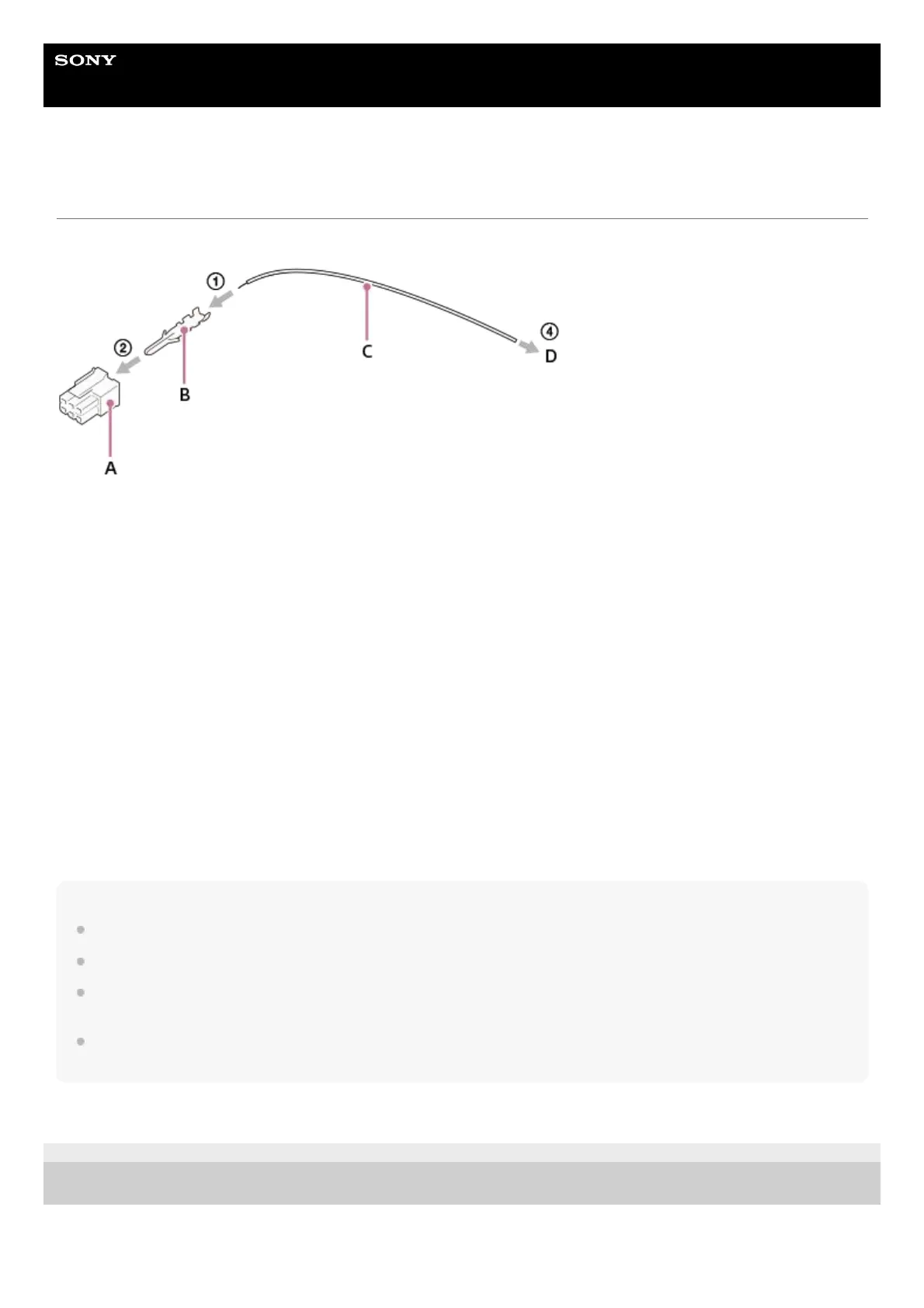
A: Molex connector
B: Molex crimp terminal
C: Lead wire
D: Connector compatible with the device to be connected
Construction procedure
Reference parts
Information on the parts used in the supplied Power & Control Cable
A: Made by Molex/430250600
B: Made by Molex/462355001
D: Made by SMK/LGP0038-0100F
Note
Use a connector and crimp terminal compatible with Molex Micro-Fit 3.0 6 pin (430450622).
Use a gold-plated crimp terminal.
Be sure to connect to the power (+)/GND (-)/FOCUS/TRIGGER/EXPOSURE terminal correctly. If you connect to the wrong
terminal, there is a risk of malfunction, smoking or fire, etc.
The usable voltage range is DC 10 V – 18 V (on the terminal side of the camera body). Calculate the impedance so as to be
within this range and construct a cable.
TP1001311882
5-055-988-11(1) Copyright 2023 Sony Corporation
Crimp the crimp terminal (B) to the lead wire (C) using a Molex crimp jig.1.
Attach the crimp terminal made in step 1 to the connector (A).2.
Repeat steps 1 and 2 depending on the number of pins to be used.3.
Connect the attachable connector (D) to the device to be connected.4.
 Loading...