45
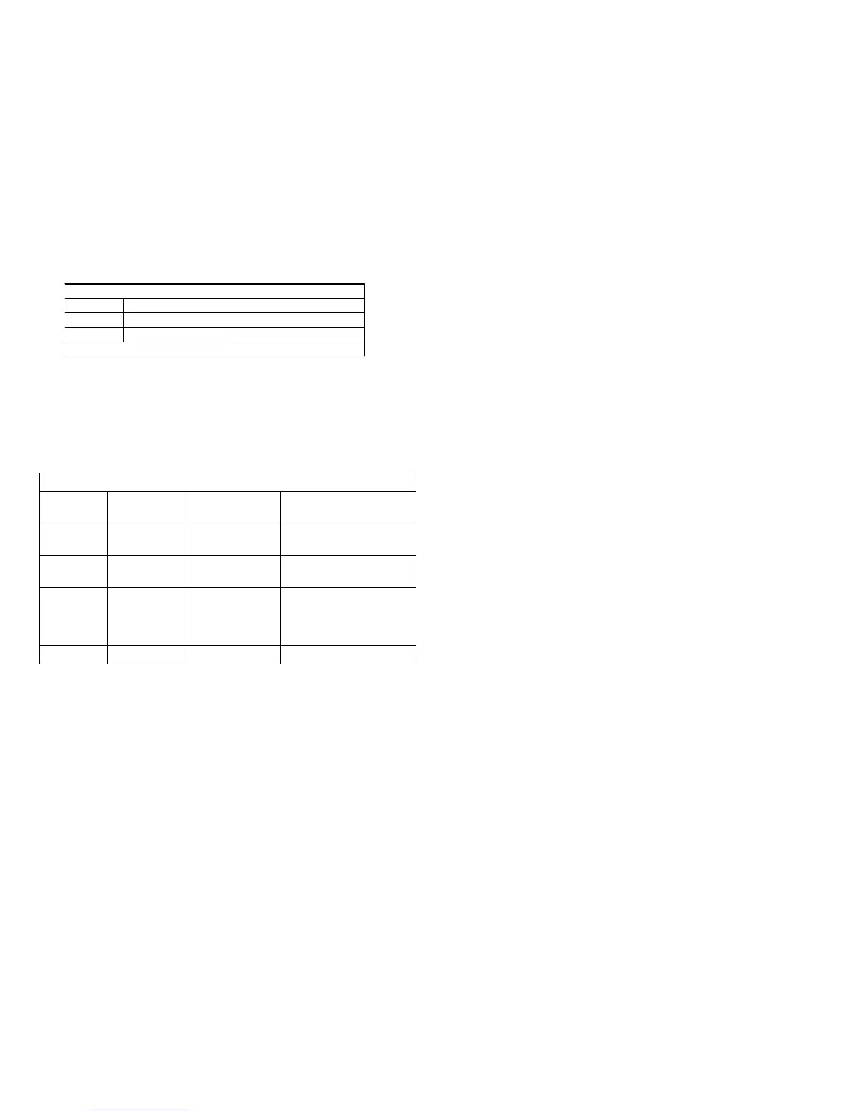
Stepper Motor Drive signals
Name Location Voltage
PA CN701/pin 1 4.3Vp-p
PNB CN701/pin 4 8Vp-p (voltage spikes)
Time Base = 20msec/div.
At track 00 a photodetector beam is crossed, marking this track. The
stepper motor stops and disc’s table of contents are read and loaded into
memory on the main board. In the Play Mode, the stepper motor immedi-
ately moves the heads into the data area to retrieve the last picture. In the
Still or Movie Modes, the heads remain at track 00 but the photodetector’s
LED is shut off to conserve power. The photodetector is connected to
CN701/pins 5-8.
Photodetector Connections
Name Location
Voltage (motor
not at track 00)
Purpose
FDD_5V CN701/pin 5 5Vdc +5V to anode of
photodetector LED.
STB Y CN701/pin 6 4.2Vdc Ground end of the
photodetector LED.
TOS 1 CN701/pin 7 4.9Vdc
Phototransistor
detector output. LOW
when track 00 is
reached.
FDD_Gnd CN701/pin 8 0Vdc Ground

 Loading...


