i
Using the RM-95 for Adjustments
Generally when the lens or imager is replaced, the camera adjustments
must also be performed. When the rear LCD panel is replaced or the PK
board is repaired, the LCD adjustments must be performed. If the main
FC-72 board is replaced, the camera, LCD and data from the old memory
must be transferred to the new board and adjustments must be performed.
This can be accomplished in one of three ways:
1. Put the two original EEPROM ICs into the new board.
2. Transfer data from both EEPROM ICs using Radar W.
3. Using Radar W, install default data from another Mavica of the same
model if the original EEPROM is bad.
RM-95 or Radar?
Both units are required for specific applications. The RM-95 is best used
for adjustments to the Mavica camera. The Radar W system is best used
to copy the bulk EEPROM data from the old board to the new board. Both
units use a CPC-12 board with cable to connect to the camera. Radar W
uses your computer to load data into the Mavica.
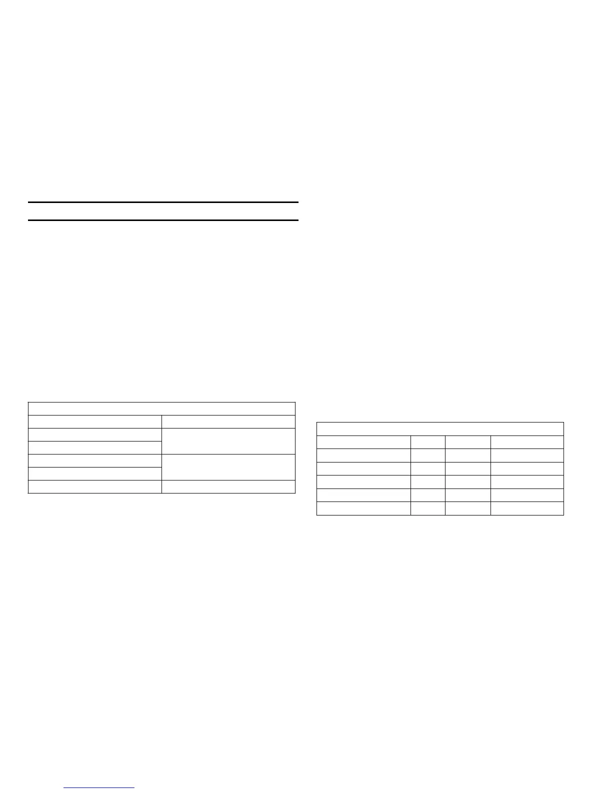
Main Usage
RM-95 Radar W
Make adjustments
Forced power ON
Upload EEPROM memor
data from the
computer to the camera.
Test function buttons Test function buttons
RM-95 - Forced Power Mode
In addition to performing adjustments, the RM-95 can also change data
on page “D” address 10 of an EEPROM and keep the FC-72 board pow-
ered ON in one of three modes. This remote power access is useful if the
camera fails to power ON normally or if you need to measure voltages
without the rear panel (PK board) connected.
Procedure
1. Connect the RM-95 to the Mavica camera. Some models have a jack
for the RM-95 while others require the CPC-12 interface jig as shown.
2. The RM-95 has a Hold slide switch in the upper left corner. Slide this
switch to the right (HOLD ON).
3. Power the Mavica from AC adapter or battery. Once HI Control IC404
on the FU-72 board receives power; it resets and communicates with
other ICs on the serial bus. With the RM-95 connected to the bus,
IC404 is instructed to remain powered ON. At this time the RM-95
display will show a centered horizontal line with 00:00:00 underneath.
4. Before proceeding you must disable the write protection so you can
change the EEPROM data (write new data in). At page 0, use the FF
or Rew buttons of the RM-95 to change the address to 01. Then use
the Play/Stop buttons to change the data at this address from 00 to
01. This disables write protect as long as you do not power down or
slide the HOLD switch to OFF.
5. Use the Edit Search buttons to move from page 0 to page d. Going
backwards with the search minus button is easier. At page d, go to
address 10. Next change the data to 01-03 depending upon what
mode in which you want the camera to remain powered up. The
camera’s power button will be bypassed.
Forced Power Data Change
Mode Page Address Data
Defeat Write Protect 0 01 01 (normal = 00)
Still Mode ON d 10
01
Play Mode ON d 10
02
Movie Mode ON d 10
03
Normal d 10 00
6. Press the RM-95’s Pause button to enter this forced power mode into
EEPROM memory. The next time you apply power the Mavica will
remain powered ON.
7. To erase the forced power mode, follow the same steps but load in 00
data at page d, address 10 and press Pause.

 Loading...


