53
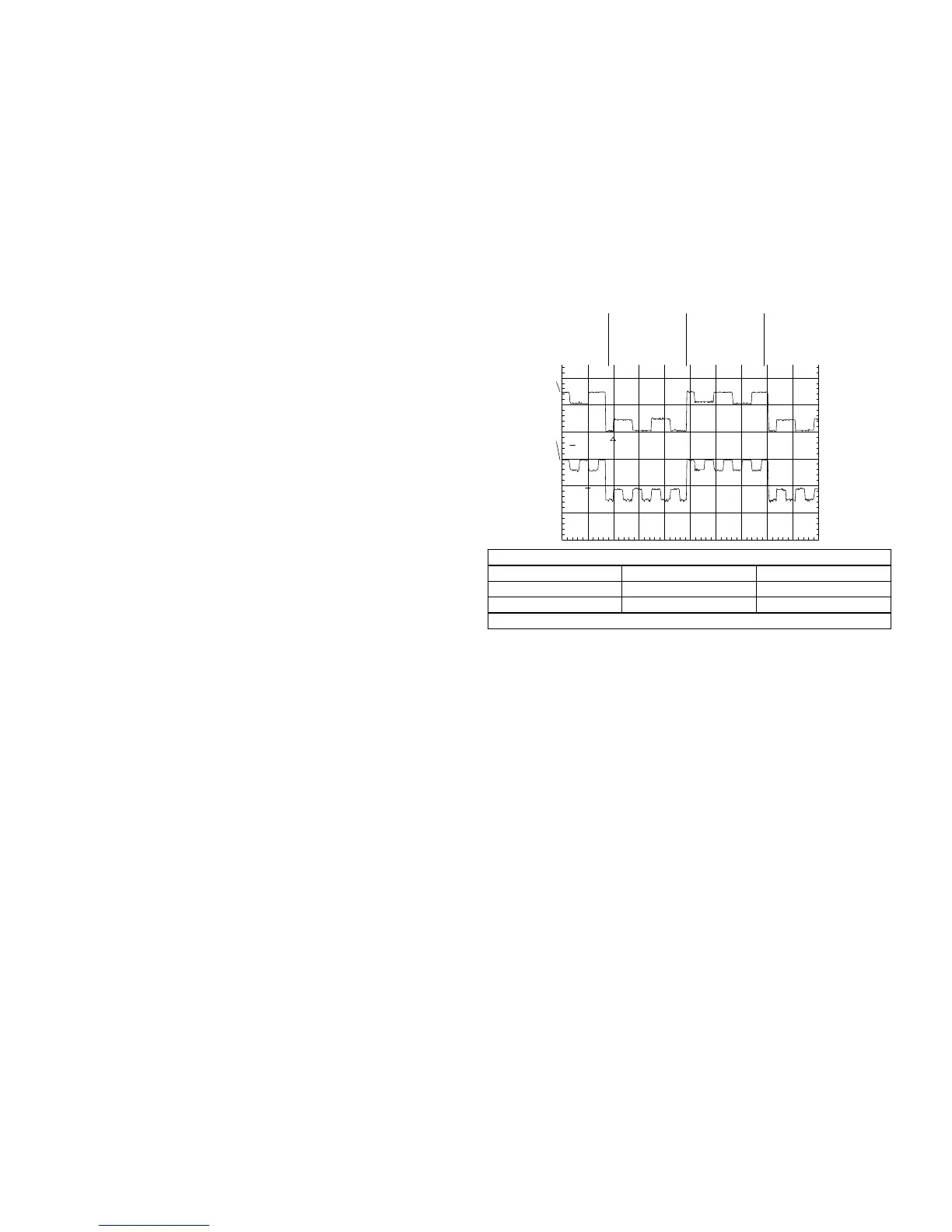
LCD Driver Output (Color Bar Floppy PB)
Name Location Voltage
Red Output IC901/pin 20 7Vp-p
Blue Output IC901/pin 24 7Vp-p
Time Base = 20usec/div.
Therefore to keep the display picture from degrading, IC901/pin 29 re-
ceives an invert signal (FRP) from the timing generator IC904/pin 9. This
signal is used by IC901 to invert every other horizontal line. By inverting
the lines, the voltage applied to the picture elements is reversed, prevent-
ing the display picture from degrading.
The result can be seen in the scope shot of the R and B output wave-
forms. Notice that portions of the R or B line are inverted. In addition to
the inverted signals, a DC reference voltage is needed to mark the center
between the inverted and non-inverted signal. This center voltage is la-
beled VCOM, and EVR IC902/pin 9 sets its level.
CH1!5 .00 V=
CH2!5.00 V= MTB20.0us- 1.98dv ch2-
1
2
T
Normal
Inverted
Normal
Inverted
Red
Blue

 Loading...


