20
3. Display Products
IN-DASH
XAV-7W
AM/FM
MEDIA
CENTER
RECEIVER
SUPPLIED
XA114
CONN.
BOX
OPTIONAL
XM SATELLITE
RADIO XT-XM1
OPTIONAL
TV TUNER
XT63V
REAR 7" FLIP
DOWN VIDEO
MONITOR
XVM-R75
OPTIONAL
DVD or VHS
PARKING
BRAKE SW.
POWER
CONTROL
CD/MD
CHANGER
SPEAKERS
AUDIO
& VIDEO
CONTROL
TO DVD
PLAYER
A/V INPUT 1 OR 2
CONTROL
VIDEO INPUT
SUPPLIED
CABLE
VIDEO OUTPUT
AUX. INPUT
XM
AUDIO
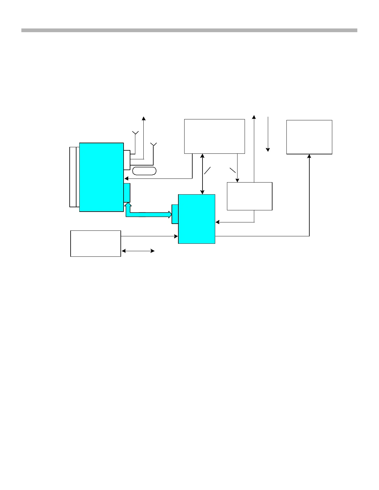
FIGURE 3-2 - MODEL XAV-7W DREAM HOOK-UP
7" LCD
DISPLAY
17A125 1535 11/19/02
PIN 13
Panel - When the car is turned Off (no longer Acc voltage), the panel retracts with battery power. As soon as the
car is turned back On, the unit recalls its last source / condition and opens the panel again (if the input battery
power was not removed). The panel need not be opened for AM/FM operation because the smaller LCD display
provides the station frequency and time. For TV or DVD display operation (video), two conditions must be met:
1) The supplied XA-114 must be connected (Figure 3-2) or you will not be able to select video 1 on the screen
with the “Source” button (only AM/FM).
2) The parking brake must be ON (Main connector CN901/pin 13 = ground) or the display will show “Picture Off
for your Safety” when Video 1 is selected.
Notes on Options –
1. When the XM satellite radio is added to the installation, the XAV-7W Reset button must be pressed or the
receiver will not recognize the XM unit in the chain.
2. A 7" monitor (Model XVM-R75) can be added to the back of the seat or on the ceiling. This panel is motorized
but is independently operated from the rear seat. Only the A/V cables feed the monitor from the supplied
external XA-114 connector box, no control signal needed.
XAV-7W – Access
Access to various parts of the Model can be easily shown with pictures.
Figure 3-3 - Unplug the XA-114 Connector box cable. Remove the top and back together.
Figure 3-4 – Unplug the top CN5 white wire connector that links the small LCD display to the main board. CN5
may be unplugged without affecting operation.
Figure 3-5 – Pry up the sides of the front bezel to remove it if the motorized front display is stuck.
Figure 3-6 – Battery and Acc power can be applied internally at CN901/pin 7 (next to end ground pin 8) and at
D918/cathode (or at the rear panel fuse, not shown).
Figure 3-7 – When the Open / Close switch is pressed, the motor runs until either end limit switch is activated.
The interim switch (switch S792 at the right pencil) limits the panel angle as the panel flips back downward.
Figure 3-8 – The monitor board may be separated from the mechanism and its power supply and backlight are
tested independently.



 To Next Page