4
1. Car Power Amplifier
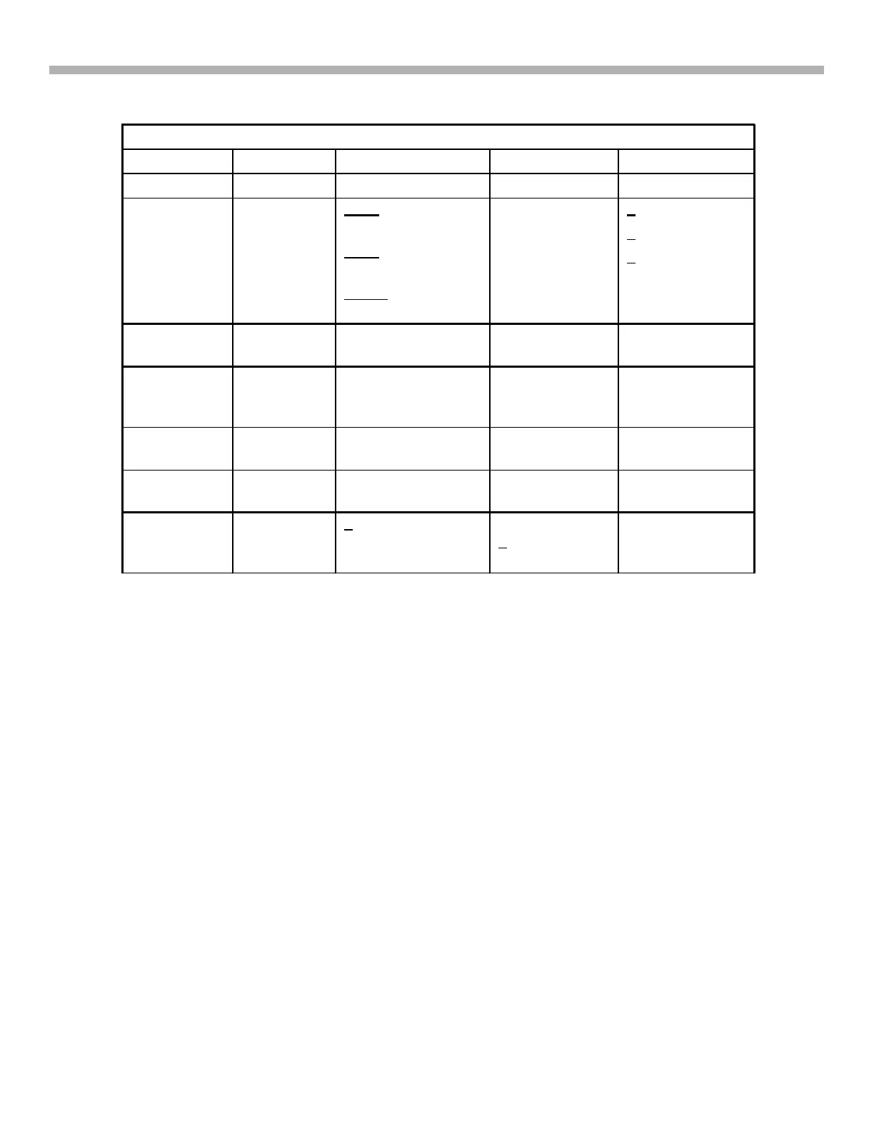
The car amplifier stages are listed in Table 1-2. The operational inputs and outputs are also listed.
Table 1-1 - Amplifier Stages (refer to Figure 1-2)
Stage Major Parts Constant Inputs Switched Inputs Output(s)
Power ON Q901-3 Battery +12V REM (7.4V min)
(Switched) +12V
DC-DC Conv IC901,
T901, Q910,
Q911.
Pin 1 = 0V (Protect
Latch 1&2).
Pin 4 = 0.6V
(Regulation input)
Pin 16 = 0.2V
(Thermistor input)
+12V +50Vdc
+14.2Vdc
+20Vdc
Audio
Process
See Fig. 1-3 Left only or left &
right channel audio.
Audio Unmute
@ power ON
Audio to
speaker(s)
Protection
Circuit 1
Q810-811
(not shown)
DC-DC Converter
voltage
Offset of
speaker output
voltage
Loss of DC-DC
Conv Output
Protection
Circuit 2
Q812-813
(not shown)
DC-DC Converter
voltage
Excessive
speaker current
Loss of DC-DC
Conv Output
Thermistors Thermistors DC-DC Converter
voltage
High case
temperature
Loss of DC-DC
Conv Output
Balance
Detector
Q912 +20V Unbalanced
+20V
supply/load
Loss of DC-DC
Conv Output
Pulse Power Supply - Power ON / Audio Unmute
Refer to Figure 1-3. Although +12V car battery power may be applied to the power amplifier, the unit will not
power ON until the REM input is applied at least 7.4Vdc. At that time, the battery +12Vdc is switched into the DC-
DC Converter stage that makes all the voltages for the power amplifier and the unit powers ON. At power ON the
audio amplifier is un-muted and both channels can operate.



 To Next Page